
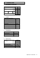
Technical data
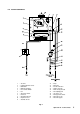


6
3.1 GAS SUPPLY
The Alpha SY24 boiler requires a gas rate of 2.71 m³/h (95.7 ft³/h).
The meter and supply pipes must be capable of delivering this quantity of gas in addition to the demand from any other
appliances in the house. The boiler requires at least a 22 mm gas supply pipe.
The complete installation, including the meter, must be tested for gas soundness and purged as described in BS 6891.
3.2 ELECTRICAL SUPPLY
The boiler requires a 230/240 V ~ 50 Hz mains supply, fused at 3 A
The boiler must be earthed.
There must only be one common isolator, providing complete electrical isolation, for the boiler and any external controls.
This boiler has been fitted with a supply cable, however, if it is necessary to fit a cable use PVC insulated cable not less than
0.75 mm² (24 x 0.2 mm) to BS 6500 Table 16. The boiler should be connected to a fused three pin plug and unswitched
shuttered socket outlet (both complying with BS 1363), or a fused double pole switch with a contact separation of at least 3 mm
in both poles.
Wiring external to the boiler must be in accordance with the current IEE Wiring Regulations (BS 7671).
Note: If a room thermostat is fitted, it must be suitable for 230/240 V switching.
3.3 AIR SUPPLY
The boiler does not require any air vents for cooling in the room in which it is installed or when installed in a cupboard or
compartment. The minimum clearances for servicing must always be maintained.
Note: A cupboard or compartment used to enclose the boiler must be designed and constructed specifically for the purpose,
i.e. comply with the Building Regulations.
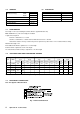
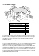
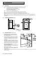
3.4 FLUE SYSTEM - Fig. 3
The flue system must be installed in accordance with BS 5440:1.
For horizontal flues ensure there is a slight downward slope towards the terminal.
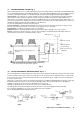
Flue components are available as follows:-
Top easy-flue 500 mm (includes 90° bend), refer to separate instructions
0.75 m flue
90° bend
45° bend
Vertical flue terminal assembly. Refer to the separate installation instructions supplied with the assembly.
A Twin Pipe Flue system is available for use with all the boilers in the range. Refer to the separate instructions for details.
The following methods determine the correct length of flue required.
For rear exit flue L = B + 175 mm
For side exit flue L = B + C + 185 mm (min. side clearance required is 5 mm)
For vertical flue L = H minus 1000 mm for vertical terminal assembly
Where L = Required flue length
B = Finished wall thickness
C = Distance from the inside wall to the side of the boiler
H = Distance from top of boiler side panel to roof position
Note: 1. If an extra 90° bend is used, this reduces the maximum flue length by 1 m. Each 45° bend used reduces the maximum
flue length by 500 mm.
2. Under no circumstances must the flue length (including allowances for extra bends) exceed 4 metres.
3. Failure to use Alpha flue components with the boiler will invalidate the boilers CE approval, guarantee and may be unsafe.
3 GENERAL BOILER INFORMATION
Alpha SY9-24 - General Boiler Information