
Instruction Manual

13
Doc. #: 0260011-J0 Rev B
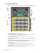
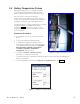
2.2 System Components
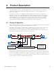
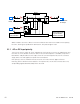
The AMPS24 HP is made up of a number of individual subsystems designed to work together to
provide highly reliable, filtered power in support of the load. A typical system contains the following:
1. Inverter AC Input Breaker: Main disconnect for AC input
2. Internal Maintenance Bypass Swi tch (MBS) ( optional): Can be used to route power directly
from the AC input to the AC output, bypassing the inverter modules.
3. Inverter AC Output Breaker: Serves as the main disconnect for the inverter AC outputs.
4. Graphi c display touch scree n: Connected to the CXCU controller by cable (see figure)
5. RJ45 cable con nector: Front panel connection for cable from the CXCU to the Graphic display
6. CXCU Unified System Controller with inte grated Ethernet/ SNMP: Monitors and manages
both inverter and rectifier modules through a web-based GUI (only 1 per unit).
7. DC Input Breakers: Individual DC input breakers for each shelf.
8. 4i or 3i+1R shelves: Up to four shelves for installing up to four hot-swappable AIM 1500
modules OR three AIM 1500 modules plus one 1800W rectifier per shelf.
9. AIM 1500 Modul es: Up to 4 AIM 1500 per 4i (4 x inverter modules) shelf or up to 3 AIM 1500
per 3i+1R (3 x inverter modules and 1 x rectifier module) shelf.
5
1
11
12
10
13
3
2
7
6
4
8
9
Figure 1 — AMPS24 HP System Components