
Instruction Manual


51
Doc. #: 0260011-J0 Rev B
Installing remaining inverters and rectifiers
30. Install the remaining inverters. The newly installed inverter modules will clone themselves to be
identical to the initial modules that were installed and set up.
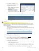
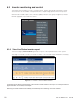
31. Select: Inverters > View Live Status at the CXCU GUI, and verify that all inverters are
recognized as follows:
a. At this point the inverter module numbers are likely random, with the largest possible inverter
number being 32 corresponding to the total number of inverter slots.
Renumber the inverter modules in some logical pattern, such as from the bottom shelf up,
using Inverters > View Live Status to locate and number each module (see Figure 30).
9 10 11 12
5 6 7 8
1 2 3 4
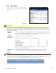
b. We recommend that you identify each physical inverter model with its corresponding inverter
number. To help identify a specific Inverter, click on the inverter row in the View Li ve Status
screen and the LEDs of that inverter will flash for a few seconds.
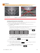
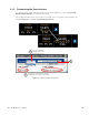
c. Select: Inverters > Group Mapping and verify that all inverters are mapped to the correct
AC Input Group and AC Output Group. If necessary, match the AC Input Group to the AC
Output Group, as shown in Figure 31.
d. Map inverters to DC Input Gro ups as discussed in section 3.6.2.
32. If the system includes the rectifier option:
a. Install one rectifier module per shelf (see Figure 1 for location) according to the instructions
in the rectifier shelf manual that ships with the unit.
b. Select: Rectifiers > View Live Status and verify that all rectifiers are recognized.
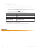
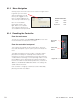
33. Use blank housings to fill slots without modules. See Figure 33.
Safe solution. Blanks must be used to cover any
open module slots.
Unsafe solution. Do not leave any module slots open.
Figure 33 — Inserting blanks in open slots
WARNING!
Use blanks to cover any open module slots. Do not leave any module slots open.