
Instruction Manual


Doc. #: 0260011-J0 Rev B
52
Final configuration and test
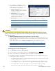
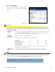
34. Using the CXCU controller web interface, configure any other parameters as required. Typical
changes could include battery and charging values for the rectifiers in a 3i+1R shelf AMPS24 HP
system or changing the low and high voltage AC and DC warning and cutout limits.
35. At this point there should be no alarms present. Investigate and correct any alarm issues.
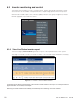
a. You will see a “communication” alarm if the number of installed inverters does not match the
number of modules set in the Inverters > Se t Output screen.
b. Refer to the Troubleshooting Chapter 8 for other alarms.
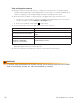
36. Test the functionality of various module alarms and controls as follows:
Test Expected result
Turn the bypass switch to BYPASS.
Bypass Mode Active alarm.
Turn off the Inverter AC Input breaker.
Inverter AC Input Breaker alarm and no change in AC output
voltage
Turn off the Inverter AC Output breaker.
Inverter AC Output Breaker Off alarm and power to loads is off
Verify the number of modules is correct
in Inverters -> Set Output.
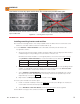
Pull out one inverter module.
Inverter Comms Lost alarm
37. Perform a system load test. Power up the equipment, one at a time. If possible, add heater or
light bulb loads to increase the load temporarily.
38. Turn off the inverter AC input breaker to perform a full load test from DC power.
WARNING!
To prevent electrical hazards such as short circuits, ensure that the system is free of debris
such as metal lings, screws, etc., after the installation is complete.