
Specifications
Master section continued
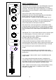
BOOTH MONITORS - This control adjusts the level of the booth monitors output which is a mix of
channels 1 to 6 only (console microphone not present in either output). The balanced outputs are via 3
pin XLR connectors. A mono signal may be obtained by using mono button located above.
INSERTS - General information
Insert sockets in the form of 3 pole 1/4” jacks are provided in pairs for the connection of external
signal processing or effects equipment. Located on the back panel the connections are:-
Tip = send (mixer output)
Ring = return (mixer input)
Body = common (ground)
Sockets are provided for effects loops 1 and 2 and the main output channels
INSERT IN / OUT - This switch allows the selection of external equipment inserted into the main insert
sockets. This affects the main and zone outputs.
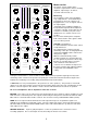
FX LOOPS 1 and 2 - Very comprehensive facilities are provided for adding external effects into the
mix. The two loops provided have identical controls.
Routing to the effects loops follows the X-fade assign buttons on channels 1 to 6.
The effects send signals may be reduced via a rear panel trimmer located above the loop connectors.
This is to ensure that overloading of sensitive input stages is avoided and the correct level is available to
effects processors.
An effects return gain trimmer ( FX1 Trim and FX2 Trim) allows the correct level to be reintroduced into
the mix.
Dry / Wet - Once enabled this control mixes between the direct signal (effects unit input) and the effects
unit output. It is provided to mix the required amount of effect. With the control set to fully Dry no effect
is added. With the control set to fully Wet just the effect return is added to the mix and the original signal
is removed. Momentary punch and latching switches enables the Wet / Dry controls.
CUE - This button allows the operator to set up the required effect on the headphones before the effect
is selected.
LOOP SWAP - This switch allows the effects processors to be swapped e.g. if just one processor was in
use and connected to FX1 ( routed from X-FA) it could be used in loop 2 (routed from X-FB)
just by depressing LOOP SWAP. The red and green l.e.d.s also change over as a reminder that Swap is
selected.
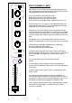
CROSSFADE - The crossfader is a 45mm fader which can be used to smoothly fade between the XF-A
and XF-B busses and any added effects.
The crossfade system uses studio quality V.C.A.’s (voltage controlled amplifiers) to improve crossfader
life and also ensure good attenuation at the ends of travel.
CONTOUR - A contour control is provided which allows the operator to adjust the crossfader
characteristics to suit personal taste, from a gentle fade between A and B to a more aggressive fade
towards the ends of the fader.
CROSSFADE OFF - An illuminated push switch operated through a hole in the front panel is fitted below
the contour control. When depressed the crossfader is disabled. Both FX1 and FX2 loops will still be
operational.
CONSOLE MIC - A dedicated microphone channel is available. The controls are positioned to the top
right corner above the headphones section.
Two band equalisation is fitted providing +/- 12dB @ 10kHz (HF) and +/- 12dB @100Hz (LF)
An illuminated ON /OFF push switch, volume control, and illuminated CUE push switch complete the
controls. This Microphone channel is not present in the booth monitors.
6