
Specifications

Operational Information or how to get the best out of your mixer
Gain
In an audio mixer different signal levels from various items of equipment need to be amplified or
attenuated to a common level so that they can be added or mixed together. These signal levels may
differ considerably depending on the equipment. The signal from a microphone, for example, may be
1000 times smaller than that from a CD player. For a mixer to be as flexible as possible and to
accept signals from a variety of equipment it is necessary for the first or early stage in the input circuit
to be a variable gain amplifier. The gain of this amplifier is set by the gain control.
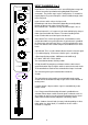
The FF-6000 has a combination of variable gain amplifiers to get the input signals to the required
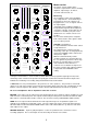
operating level. Gain trim presets are fitted - 1 for each input. These are accessible through holes on
the back panel and are labelled accordingly. The stereo input gain trims are conventional single turn
controls. The Mic preset is a multi-turn trimmer. These trims should be adjusted to set the maximum
gain available for any input. The front panel gain control works in conjunction with these presets. The
system may be considered as coarse gain control on the rear presets and fine adjustment on the front
gain control.
When amplifier gain is introduced in a circuit noise is also introduced. (This is a fact - you cannot have
one without the other). The FF-6000 has been designed to keep this noise as low as possible by using
the latest technology. For the best performance set the gain control as low as possible to achieve the
desired output level. Gain introduced into the system and then held on the channel fader is a waste of
performance. Too much gain could result in overloading the first stage causing distortion and clipping.
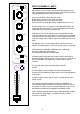
A clip indicator has been included and is located below the front panel gain control. This indicator
flashes when the signal level is close to clipping. It monitors the signal at various points in the signal
chain, therefore, gain introduced by the equalisation or tone controls is also considered.
IF THE PEAK INDICATOR ILLUMINATES DURING USE TURN DOWN THE GAIN CONTROL (OR
INPUT TRIM PRESETS).
INSTALLATION, CONNECTIONS AND GOOD WIRING PRACTICE
The installation of professional audio systems should be left to experienced engineers wherever
possible. The interconnection of audio systems can be fairly complex depending on the type and size
of system and obviously well outside the scope of this handbook. We have included a few basic
points for information for anyone who is new to audio systems.
Good wiring practice should be observed when connecting any audio equipment. Good quality
connectors and screened cable should be used for all audio connections .
Twin screened cable should be used for all balanced lines particularly microphone connections.
Always ensure cable clamps in connectors are fully tightened and gripping the outer sheath. Good
strain relief and mechanically sound connections will increase reliability at virtually no extra cost.
GROUND LOOPS
In our experience this is the most common problem encountered when connecting together different
items of audio equipment. It is the most common cause of hum (50Hz noise) on a system and is
caused by incorrect system grounding.
When several items of audio equipment are connected together with unbalanced connections (i.e. 2
connections, single screened cable, etc.) the signal common connection is the screen and this will be
connected to mains earth at some point. If several items of equipment have their signal common
connected to mains earth this will form a loop (hence ground loop). Current will flow in this loop and
appear in the form of hum (50Hz mains frequency) added to the audio signal. The problem is
aggravated if the equipment is located a distance apart as the loop is larger. It is possible to have
several ground loops within a system.
The solution is to connect the system to mains ground
only once
. This is usually done at the mixer. You will need to investigate the various items of
equipment you are using and isolate their signal common from mains earth. Many manufacturers fit a
ground lift switch for this purpose. On some equipment this is in the form of a removable link.
Unfortunately with some equipment you have to get inside to identify where the connection is and
remove it.
You must not disconnect the mains earth wire from the mains plug of any equipment. This is
fitted for safety reasons and must be connected to ensure that the case is earthed.
7