
User`s guide
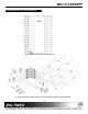

MULTI-TASKER
6
Cn = card ID (n = a slot # from 1 to 19)
(1 to 8 for MT100-101 or 1 to 2 for MT100-102)
Ui = unit id (i = 0 to 9) (refer to the MT100-100
user’s guide for explanation)
Example:
If one MT105-112/119 card is in slot #4 of unit 3
with output 1, 2 and 3 ON:
When sending command
[C4U3], feedback will
be returned as:
CONFIG: 16x16 VIS:ON
In1 Out1 ON
In2 Out2 ON
.
.
.
In1 Out16 OFF
Description of Feedback:
Input1 is connected to Output1 and Output1 is
enabled
Input2 is connected to Output2 and Output2 is
enabled
.
.
.
Input1 is connected to Output16 and Output16 is
disabled
Note: If there is no card in slot #4 of unit 3,
sending the
[C4U3] command will not return any
feedback.
ERROR CODES
ER01: CPU Error
This type of error indicates that the CPU is not
working properly.
ER02: I²C Communication Error
This means that the communication between the
MT105-112/119 card and its serial device has
failed.
ER03: RS485 Communication Error
This type of error is a communication error
between the MT105-112/119 card and the
controller of the Multi-Tasker™ Enclosure.
3. [CiS]
This command saves card status as default
configuration, such as ON / OFF, IN / OUT. The
next time card will be activated this configuration
will be loaded in.
4. [IO]
This command will connect input x with output y,
but the user needs to use the [ON] command to
enable this output.
Command Format: [IxOyCnUiS]
Ix = select input x (x is # from 1 to 16)
Oy = connect to output y (y is # from 1 to 8)
Cn = card ID number (n is # from 1 to 19) (1 to 8
for MT100-101 or 1 to 2 for MT100-102)
Ui = unit ID (i is # from 0 to 9). (Refer to MT100-
100 user’s guide to set Unit ID).
S = saves command to memory
Example:
To connect input 4 to output 2 (card 4 of unit 3),
use the [I4O2C4U3] command.
[ImO*…]
This command connects input m to all outputs.
5. [ON]
This command enables output of a single card or
a group of cards.
[ONmCnUiS]: for a single card
This command enables output “m” without
affecting any other outputs.
Default when plugged in = ALL OFF
m = Output number (m = 1 to 16)
n = Card ID number (n = 1 to 19) (1 to 8 for
MT100-101 or 1 to 4 for MT100-106)
i = Unit ID number (i = 0 to 9)
S = saves command to memory
Example:
1)
[ON12C5U3]: Turns ON only output 1 and 2 of
the MT105-112/119 card located in slot #5 of the
MT100-100 Enclosure with unit ID3.