MULTI-TASKER™ MANUAL PART NUMBER: 400-0353-001 MT107-301/305/306 8 BNC OUTPUTS 450MHz VIDEO, SYNC/VIDEO, SYNC FOR MULTI-TASKER™ MATRIX SWITCHER USER’S GUIDE
MULTI-TASKER™ TABLE OF CONTENTS Page PRECAUTIONS / SAFETY WARNINGS.............. 2 GENERAL ................................ ......................... 2 INSTALLATION ................................ ................. 2 CLEANING ................................ ........................ 2 FCC / CE NOTICE................................ ............. 2 ABOUT YOUR MT107-301/305/306 .................... 3 TECHNICAL SPECIFICATIONS .......................... 3 PRODUCT DESCRIPTION................................ ..
MULTI-TASKER™ PRECAUTIONS / SAFETY WARNINGS 1 • This equipment has been tested and found to comply with the limits for a Class A digital device, pursuant to Part 15 of the FCC Rules. These limits are designed to provide reasonable protection against harmful interference when the equipment is operated in a commercial environment.
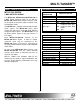
MULTI-TASKER™ ABOUT YOUR MT107-301/305/306 2 TECHNICAL SPECIFICATIONS MT107–301/305/306 FEATURES/ DESCRIPTION GENERAL Outputs Output Connectors Compatibility 8 BNC OUTPUTS 450MHz The MT107-301, MT107-305 and MT107-306 are 8 BNC Output expansion cards for use with the MT107-100 64X64 Matrix Engine. All three cards are designed to work with signal resolutions from VGA through UXGA.
MULTI-TASKER™ PRODUCT DESCRIPTION 4 4
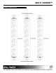
MULTI-TASKER™ APPLICATION DIAGRAM 5 DIAGRAM 1: TYPICAL CONFIGURATION 5
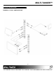
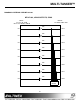
MULTI-TASKER™ DIAGRAM 2 INTERNAL VIEW MT107-301 MT107-301, 8 BNC OUTPUTS 450MHz, VIDEO/SYNC INPUTS 40 PIN IDC FROM MT107-100 MATRIX ENGINE OUTPUTS TO FRONT PANEL BNCs VIDEO OUT1 IN1 SYNC VIDEO OUT2 IN2 SYNC VIDEO OUT3 IN3 SYNC VIDEO OUT4 IN4 SYNC VIDEO OUT5 IN5 SYNC VIDEO IN6 OUT6 SYNC VIDEO OUT7 IN7 SYNC VIDEO OUT8 IN8 SYNC 6 SIGNAL DETECT
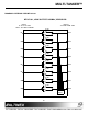
MULTI-TASKER™ DIAGRAM 3 INTERNAL VIEW MT107-305 MT107-305, 8 BNC OUTPUTS 450MHz, VIDEO INPUTS 40 PIN IDC FROM MT107-100 MATRIX ENGINE OUTPUTS TO FRONT PANEL BNCs VIDEO OUT1 IN1 VIDEO OUT2 IN2 VIDEO OUT3 IN3 VIDEO OUT4 IN4 VIDEO OUT5 IN5 VIDEO IN6 OUT6 VIDEO IN7 OUT7 VIDEO OUT8 IN8 SIGNAL DETECT 7
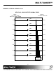
MULTI-TASKER™ DIAGRAM 4 INTERNAL VIEW MT107-306 MT107-306, 8 BNC OUTPUTS, SYNC INPUTS 40 PIN IDC FROM MT107-100 MATRIX ENGINE OUTPUTS TO FRONT PANEL BNCs SYNC OUT1 IN1 SYNC OUT2 IN2 SYNC OUT3 IN3 SYNC OUT4 IN4 SYNC OUT5 IN5 SYNC IN6 OUT6 SYNC IN7 OUT7 SYNC OUT8 IN8 SIGNAL DETECT 8
MULTI-TASKER™ INSTALLING YOUR MT107-301/305/306 6 OPERATION Step 1. Locate the MT107-100 currently installed in the Multi-Tasker™. Ensure there are enough empty slots in the enclosure to allow for the one or more MT107-301/305/306's to be installed. 7 7.1 RS-232 CONTROL The MT107-301/305/306 has many advanced remote control capabilities when used in the Multi-Tasker™ Enclosure as part of an MT107-100 Matrix Switcher. These capabilities are accessible through standard RS-232 communication.
MULTI-TASKER™ 8.2 NO DISPLAY Cause 5: The display has a problem. Solution: Cause 1: The source has a problem. Solution: Check the source and make sure that there is a signal present and all source connections are correct. If the source is working and there is still no display, see Cause 2. Make sure the display has power and is turned ON. If there is still no display, please call Altinex at (714) 990-2300. ALTINEX POLICY 9 Cause 2: The output signal is not detected. 9.