DESIGNER SOLUTIONS Shown with a silver finish.
DESIGNER SOLUTIONS TABLE OF CONTENTS Page PRECAUTIONS / SAFETY WARNINGS................ 2 GENERAL..........................................................2 HANDLING ........................................................2 CLEANING.........................................................2 FCC NOTICE .....................................................2 ABOUT YOUR PNP400 ............................................ 3 TECHNICAL SPECIFICATIONS.............................. 3 PRODUCT DESCRIPTION .............
DESIGNER SOLUTIONS PRECAUTIONS / SAFETY WARNINGS 1.3 CLEANING 1 Please read this manual carefully before using your PNP400 and keep it handy for future reference. These safety instructions are to ensure the long life of your PNP400 and to prevent fire and shock hazards. Please read them carefully and heed all warnings. • 1.1 GENERAL • • • Clean only with a dry cloth. Never use strong detergents or solvents such as alcohol or thinner. Do not use a wet cloth or water to clean the unit.
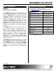
DESIGNER SOLUTIONS ABOUT YOUR PNP400 2 TECHNICAL SPECIFICATIONS Specifications are subject to change. See www.altinex.com for up-to-date information. PNP400 POP 'N PLUG TOWER MECHANICAL The PNP400 Interconnect Tabletop Solution is designed for installation into a conference room table. The PNP400 provides a means of connecting audiovisual, network, and power sources into a presentation system. It is ideal for use with ALTINEX computer video interfaces like the VA6804FC.
DESIGNER SOLUTIONS PRODUCT DESCRIPTION 4 POP-UP LID MOUNTING HOLES FOR ACCESSORY PLATES (front and back) GAS SPRING BEZEL TABLETOP THUMB SCREW MOUNTING BRACKET CHASSIS 400-0109-006 4
DESIGNER SOLUTIONS APPLICATION DIAGRAMS 5 DIAGRAM 1: TYPICAL SETUP 400-0109-006 5
DESIGNER SOLUTIONS DIAGRAM 2: CUTOUT 400-0109-006 6
DESIGNER SOLUTIONS DIAGRAM 3: TOP VIEW 6.530" [166mm] 7.
DESIGNER SOLUTIONS DIAGRAM 4: FRONT VIEW 2.909" [74 mm] 5.760" [146 mm] 6.
DESIGNER SOLUTIONS DIAGRAM 5: SIDE VIEW 2.909" [74 mm] 5.760" [146 mm] 4.
DESIGNER SOLUTIONS DIAGRAM 6: MOUNTING 2 MOUNTING BRACKETS MOUNTING BRACKETS DETAILS TOP VIEW SIDE VIEW 2 THUMB SCREWS SIDE VIEW TABLETOP Install the mounting brackets into the grooves on both sides of the unit using the grooves that best fit the thickness of the tabletop. Thread the thumb screws through the mounting brackets as shown until the PNP400 is securely mounted to the tabletop.
DESIGNER SOLUTIONS DIAGRAM 7: ACCESSORY INSTALLATION ALIGN MOUNTING HOLES FEED CABLES THROUGH FRONT AND DOWN THROUGH CHASSIS (SP3201AV shown here.) PLASTIC RIVETS Insert this side through holes until it sits flush with the metal. FASTEN WITH PLASTIC RIVETS BEFORE AFTER 1 Feed any cables attached to the sectional plate through the front of the PNP400, then down through the opening in the bottom of the chassis. Make sure the cables exit the chassis on the same side as the plate.
DESIGNER SOLUTIONS DIAGRAM 8: CABLES/ACCESSORIES Model No.
DESIGNER SOLUTIONS INSTALLING YOUR PNP400 Step 7. Secure the power cord using the cable clamp provided. Pass the power cord (if any) from the bottom of the housing and attach it to the table leaving a service loop beneath the unit. Before tightening the clamp, open and close the unit from the top several times. Set the service loop for smooth operation only. Do NOT leave excessive cable hanging below the table. 6 Step 1. Refer to the ALTINEX website, www.altinex.
DESIGNER SOLUTIONS OPERATION 7 ALTINEX POLICIES 7.1 INSTALL SECTIONAL PLATES 9.1 LIMITED WARRANTY/RETURN POLICIES Install sectional plates in the empty slots on each side of the PNP400 until the plates snap into place. Secure the plates using the plastic, removable rivets as shown in DIAGRAM 7. TROUBLESHOOTING GUIDE Please see the ALTINEX website at www.altinex.com for details on warranty and return policies. 9.2 CONTACT INFORMATION ALTINEX, Inc.