
User Manual

5
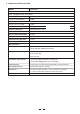
3. CONTROL ELEMENTS
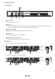
3.1 Front Panel
Power Switch
Turn the unit power on or off.
Clip LED
When the signal distortion reaches or surpasses 0.5%, the LED lights up. This means the output level of signal
source is too high and it is time to reduce input level until clip LED turning off.
Output Limiter LED
While the unit is limiting the output signal, the LED lighting up.
Power LED
This LED lights up when the unit is powered.
Level Control for Channels1&2
Adjust the output signal level to avoid signal distortion.
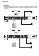
A. rear panelThis is set for 220V AC TO 240V AC
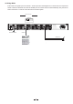
3.2 Rear Panel
1
2
3
4
5
1
2
3
5
4
5
LTO
R
CH2
INPUT
CH1
POWER
OUTPUTS
LIMITER
OFF
ON
TIP
SP
SP
TIP
SP
SP
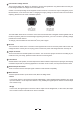
MODE
BRIDGE
STEREO
TIP/PIN 2
RING/PIN 3
SLEEVE/PIN 1
TIP/PIN 2
RING/PIN 3
SLEEVE/PIN 1
CH1
1+ 1-
POS NEG
CH2
2+ 2-
POS NEG
BRIDGE
1+ 2+
POS NEG
CH2
1+ 1-
POS NEG
21
3
NEW TIDE
21
3
NEW TIDE
CH2 CH1
Use only with a 250V fuse
Rated Power Consumption 200W
REPLACE FUSE WITH CORRECT TYPE ONLY
Apparaten skall anslutas
ansluts till ett natverk
till jordat uttag nar den
FUSE: T1.6AL 250VAC
AC INPUT: 220-240V 50-60Hz
6 7
11
10
9
8
B. rear PanelThis is set for 110V AC TO 120V AC
CH2
INPUT
CH1
POWER
OUTPUTS
LIMITER
OFF
ON
TIP
SP
SP
TIP
SP
SP
MODE
BRIDGE
STEREO
TIP/PIN 2
RING/PIN 3
SLEEVE/PIN 1
TIP/PIN 2
RING/PIN 3
SLEEVE/PIN 1
CH1
1+ 1-
POS NEG
CH2
2+ 2-
POS NEG
BRIDGE
1+ 2+
POS NEG
CH2
1+ 1-
POS NEG
21
3
NEW TIDE
21
3
NEW TIDE
CH2 CH1
Use only with a 250V fuse
AC INPUT: 110-120V 50-60Hz
FUSE: T3.15AL 250VAC
Rated Power Consumption 200W
REPLACE FUSE WITH CORRECT TYPE ONLY
Apparaten skall anslutas
ansluts till ett natverk
till jordat uttag nar den
Class
two wiring
Class
two
wiring
6 7
11
10
9
8