
User Manual
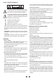
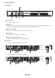
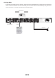

CH2
INPUT
CH1
POWER
OUTPUTS
LIMITER
OFF
ON
TIP
SP
SP
TIP
SP
SP
MODE
BRIDGE
STEREO
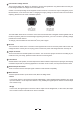
TIP/PIN 2
RING/PIN 3
SLEEVE/PIN 1
TIP/PIN 2
RING/PIN 3
SLEEVE/PIN 1
CH1
1+ 1-
POS NEG
CH2
2+ 2-
POS NEG
BRIDGE
1+ 2+
POS NEG
CH2
1+ 1-
POS NEG
21
3
NEW TIDE
21
3
NEW TIDE
CH2 CH1
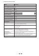
Use only with a 250V fuse
Rated Power Consumption 200W
REPLACE FUSE WITH CORRECT TYPE ONLY
Apparaten skall anslutas
ansluts till ett natverk
till jordat uttag nar den
FUSE: T1.6AL 250VAC
AC INPUT: 220-240V 50-60Hz
CH2
INPUT
CH1
POWER
OUTPUTS
LIMITER
OFF
ON
TIP
SP
SP
TIP
SP
SP
MODE
BRIDGE
STEREO
TIP/PIN 2
RING/PIN 3
SLEEVE/PIN 1
TIP/PIN 2
RING/PIN 3
SLEEVE/PIN 1
CH1
1+ 1-
POS NEG
CH2
2+ 2-
POS NEG
BRIDGE
1+ 2+
POS NEG
CH2
1+ 1-
POS NEG
21
3
NEW TIDE
21
3
NEW TIDE
CH2 CH1
Use only with a 250V fuse
Rated Power Consumption 200W
REPLACE FUSE WITH CORRECT TYPE ONLY
Apparaten skall anslutas
ansluts till ett natverk
till jordat uttag nar den
FUSE: T1.6AL 250VAC
AC INPUT: 220-240V 50-60Hz
7
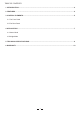
4. APPLICATION
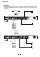
4.1 Stereo Mode
In this mode, Channel 1 and Channel 2 operate independently ( just as traditional stereo amplifier). The signal
input into channel 1 can be output from channel 1 only, similarly, the signal input into channel 2 can be output from
channel 2 only.
Total two optional modes:
Please see following diagram for connecting the power amplifier into your audio system.
1
2
3
GND
INPUT
+
Input Connector
Balanced
Channel 1
+
Channel 2
1
2
3
GND
INPUT
Input Connector
Balanced
Channel 1
Channel 2
Channel 1
Channel 2
+
Channel 1
+
Channel 2
MODE
Release this button
MODE
Release this button