Holding Cabinet Deluxe or Simple Control Models: 300-s 5 00-s 750-s 1000-s 1200-s 1000-UP 1200-UP 1200-UP 1000-UP 1200-s 1000-s • Installation 750-s 500-s 300-s • Operation • Maintenance W164 N9221 Water Street • P.O. Box 450 • Menomonee Falls, Wisconsin 53052-0450 USA PHONE: 262.251.3800 • 800.558.8744 USA / CANADA FAX: 262.251.7067 • 800.329.8744 U . S . A . www.alto-shaam.com printed in u.s.a.
Delivery . . . . . . . . . . . . . . . . . . . . . . . . . . . . . . . . . . . . . . . . . 1 Unpacking . . . . . . . . . . . . . . . . . . . . . . . . . . . . . . . . . . . . . . . 1 Safety Procedures and Precautions . . . . . . . . . . . . . . . . . . . 2 Sanitation Sanitation/Food Safety. . . . . . . . . . . . . . . . . . . . . . . . . . 22 Internal Food Product Temperatures. . . .
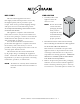
DelIVery UnPaCKIng This Alto-Shaam appliance has been thoroughly tested and inspected to ensure only the highest quality unit is provided. Upon receipt, check for any possible shipping damage and report it at once to the delivering carrier. See Transportation Damage and Claims section located in this manual. This appliance, complete with unattached items and accessories, may have been delivered in one or more packages.
SaFety ProCeDUreS anD PreCaUtIonS Knowledge of proper procedures is essential to the safe operation of electrically and/or gas energized equipment. In accordance with generally accepted product safety labeling guidelines for potential hazards, the following signal words and symbols may be used throughout this manual. Danger Used to indicate the presence of a hazard that WILL cause severe personal injury, death, or substantial property damage if the warning included with this symbol is ignored.
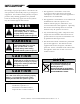
installation Danger CaUtIon IMPROPER INsTALLATION, ALTERATION, ADJUsTMENT, sERVICE, OR MAINTENANCE COULD REsULT IN sEVERE INJURY, DEATH, OR CAUsE PROPERTY DAMAGE. READ THE INsTALLATION, OPERATING AND MAINTENANCE INsTRUCTIONs THOROUGHLY BEFORE INsTALLING OR sERVICING THIs EQUIPMENT. CaUtIon TO PREVENT PERsONAL INJURY, METAL PARTs OF THIs EQUIPMENT BECOME EXTREMELY HOT WHEN IN OPERATION. TO AVOID BURNs, ALWAYs UsE HAND PROTECTION WHEN OPERATING THIs APPLIANCE.
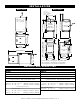
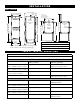
Model 300-S Model 500-S Cord Length: 120V - 5' (1524mm) 208-240V - 8' (2438mm) 230V - 8' (2438mm) 16-3/4" (426mm) 58-11/16" (1490mm) Pass-Through Option Electrical Connection Electrical Connection Pass-Through Option 30-7/16" (772mm) 28-13/16" (731mm) 14-3/8" (365mm) 5-5/16" (134mm) 33-9/16" (852mm) with 3-1/2" (89mm) casters* 300-s 2011 lit 300-s 2011 lit 16-3/4" (426mm) 16-3/4" (426mm) 3/4" (19mm) 18-15/16" (480mm) 3/4" (19mm) 18-15/16" (480mm) 18-3/4" (477mm) 18" (458mm) 3/4" (19mm) 18-1
I N S TALLAT I ON Model 750-S Model 1000-S Cord Length: 120V - 5' (1524mm) 208-240V - 8' (2438mm) 230V - 8' (2438mm) Cord Length: 120V - 5' (1524mm) 208-240V - 8' (2438mm) 230V - 8' (2438mm) 25-1/16" (636mm) 70-5/8" (1844mm) Shown with optional bumper Pass-Through Option Electrical Connection 23-1/4" (591mm) 30-3/8" (771mm) Pass-Through Option 23-5/8" (600mm) 26-5/8" (676mm) Electrical Connection 37-3/16" (944mm) 5-5/16" (134mm) 33-9/16" (852mm) with 3-1/2" (89mm) casters* Electrical Connect
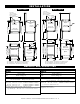
I N S TALLAT I ON Model 1000-UP Model 1200-S Cord Length: 120V - 5' (1524 mm) 208-240V - 8' (2438 mm) 230V - 8' (2438 mm) Cord Length: 120V - 9' (2743mm) 208-240V - 8' (2438mm) 230V - 8' (2438mm) 77-15/16" (1979mm) Shown with optional bumper Pass-Through Option Electrical Connection 34-3/16" (867mm) 17-1/16" (433mm) Electrical Connection Pass-Through Option 24-1/8" (613mm) 23-1/16" (585mm) 24-1/8" (613mm) 24" (608mm) 16-15/16" (429mm) 6-13/16" (173mm) 44" (1117mm) with 5" (127mm) casters* 6-1
77-15/ 54-1/4" (137 34-1/ 56-1/4" (14 optional bumper I N S TALLAT I ON Model 1200-UP 33-13/16" (858mm) 25-13/16" (655mm) 16-7/8" (429mm) 25-1/16" (636mm) Cord Length: 120V - 9' (2743mm) 208-240V - 8' (2438mm) 230V - 8' (2438mm) 27-5/8" (701mm) 77-15/16" (1979mm) 54-1/4" (1377mm) Shown with optional bumper 16-7/8" (429mm) w eight 333 lb (151g) net : ship : ( est .
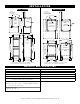
I N S TALLAT I ON UNIVERSAL PAN SLIDES Shown with universal pan slides. Two (2) slides needed per pan. Universal Pan Slides, SR-24762, stainless steel SR-24447, chrome plate Side Rail 1011741 SIDE RACKS AND SHELVES (optional) As an alternative to universal pan slides, this unit can be ordered as a “side rack” model which is equipped with two (2) side racks and three (3) chrome plated wire shelves.
I N S TALLAT I ON O P T I ON S a n d A C C E S S OR I E S m o d el > 300-s 500-s 750-S —— 5011161 5010371 HL-2635 HL-2635 HL-2635 DESCRIPTION 1000-s 1200-S 1000-UP 1200-UP 5009767 5012932 5009767 5012932 —— —— —— —— PART Number Bumper, Full Perimeter Carving Holder, Prime Rib Carving Holder, Steamship (Cafeteria) Round —— 4459 4459 —— —— —— —— Caster Package 2-1/2" (64mm) —— 5008022 5008022 5008022 —— —— —— 3-1/2" (89mm) —— standard standard standard 50080
installation StaCKIng InStrUCtIonS 1) If the two appliances were shipped together from the factory, the top unit will have the casters already removed. a stacking kit will be included with the shipment. If casters need to be removed: lay the unit on its back, and remove the set screw on each caster. Pull the casters out of the unit. 2) while appliance is laid on its back, insert one stacking post in each of the four corners of the upper unit.
I N S TALLAT I ON S I TE I N S TALLAT I ON A number of adjustments are associated with initial installation and start-up. It is important that these adjustments be conducted by a qualified service technician. Installation and start-up adjustments are the responsibility of the dealer or user. These adjustments include but are not limited to thermostat calibration, door adjustment, leveling, electrical hook-up and installation of optional casters or legs.
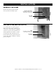
installation si t e I N S TALLAT I ON drip tray installation instructions - 500, 750, 1000, 1200 b a d c Item 1 1. 2. 3. 4. 5. Description Double-Sided Tape Drip Tray Holder 1 3 8-32 x 1/4" Phil Screw 3 4 Drip Tray 1 warnIng FaIlUre to ProPerly InStall tHe DrIP tray Can or wIll CaUSe MaJor eQUIPMent DaMage anD wIll reSUlt In a leaKage HaZarD tHat Can CaUSe PerSonal InJUry.
I N S TALLAT I ON ELE C TR I C AL 1. An identification tag is permanently mounted on the cabinet. 2. Plug cabinet into a properly grounded receptacle ONLY, positioning the unit so the power supply cord is easily accessible in case of an emergency. Arcing will occur when connecting or disconnecting the unit unless all controls are in the “OFF” position. 3.
I N S TALLAT I ON ELE C TR I C AL 300- S 1 2 0 0 -S kW & cord 120 1 60 6.7 .80 nema 5-20 p 20A-125 v plug 230 1 50/60 3.9 .80 cee 7/7 220-230 v plug 500-S voltage phase cycle / hz amps kW 120 1 60 8.4 1.0 & cord nema plug 5-15 p , 15A-125 v plug 208 1 60 3.7 .76 nema 6-15 p , 15A-250 v plug 240 1 60 4.2 1.0 (USA ONLY) 230 1 50/60 4.1 .95 cee 7/7, 220-230 v plug 750-S voltage phase cycle / hz amps kW 120 1 60 9.0 1.
I N S TALLAT I ON U S ER I N F OR M AT I ON USER SAFETY INFORMATION BEFORE INITIAL USE: This appliance is intended for use in commercial establishments where all operators are familiar with the purpose, limitations, and associated hazards of this appliance. Operating instructions and warnings must be read and understood by all operators and users. 1. U nit must be connected to the appropriate power source. 2. Use hand protection when handling hot items. 3. Preheat the unit for 30 minutes before use. 4.
operation O P ERAT I NG I N S TR U C T I ON S 1. P REHEAT AT 200°F (93°C) for 30 minutes before loading food. Push power switch to “On” position. The unit will begin operating at the previous set temperature. 2. Press the Up or Down Arrow Keys to 200°F (93°C). Pressing and releasing the Arrow Keys will increase the set point by 1 degree. Pressing and holding the Arrow Key will increase set point by 10 degrees. When Arrow Key is released, a new set point temperature is set.
O P ERAT I ON D EL U X E C ONTROL O P T I ON 1 power on indicator light 6 o n / off key 2 heat indicator 3 led display 4 lock indicator 5 u p / down 1 power on indicator light 6 o n / off key 2 heat indicator 3 led display 4 lock indicator 5 u p / down arrow keys arrow keys upper lower Double Compartment Control Deluxe Control With multiple timers 7 shelf timer keys D EL U X E C ONTROL S ET - U P on/off Key Press the on/off key once and the power indicator light will illuminate.
O P ERAT I ON D EL U X E C ONTROL O P ERAT I ON 1. Preheat at 200°F (93°C) for 30 minutes. P ress the ON key, and set the temperature to 200°F (93°) by using the UP/DOWN arrow keys. Allow a minimum of 30 minutes preheating time before loading the holding cabinet with food. Closing the vents on the inside of the door will speed the preheating process.
O P ERAT I ON D ELU X E C ONTROL TI MER PROGRAMMI NG Timer Programming Information 1. Turn On/Off Control Key OFF. Press the On/Off Key until the display turns OFF (at least 3 seconds) and On/Off Key’s Power Indicator Light goes out. Note: T he following steps can only be done when the Control is OFF. 2. Set Shelf Timer Keys. Press and hold a Shelf Timer Key (at least 3 seconds) until the countdown time is shown in the LED display. Use the Up or Down arrow key to change the time desired.
O P ERAT I ON GENERAL H OLDING GUID EL INES Chefs, cooks and other specialized food service personnel employ varied methods of cooking. Proper holding temperatures for a specific food product must be based on the moisture content of the product, product density, volume, and proper serving temperatures. Safe holding temperatures must also be correlated with palatability in determining the length of holding time for a specific product.
C ARE AN D C LEAN I NG CleanIng anD PreVentatIVe MaIntenanCe ProteCtIng StaInleSS Steel SUrFaCeS It is important to guard against corrosion in the care of stainless steel surfaces. Harsh, corrosive, CleanIng agentS Use non-abrasive cleaning products designed for use on stainless steel surfaces. Cleaning agents must be chloride-free compounds and must not or inappropriate chemicals can completely destroy the contain quaternary salts. Never use hydrochloric acid (muriatic acid) on stainless steel surfaces.
C ARE AN D C LEAN I NG The cleanliness and appearance of this equipment will contribute considerably to operating efficiency and savory, appetizing food. Good equipment that is kept clean works better and lasts longer. CLEAN THE HOLDING CABINET DAILY: 1. Disconnect unit from power source, and let cool. 2. Remove all detachable items such as shelves, side racks, and drip pan. Clean these items separately with a good grease solvent or commercial detergent. Rinse well and dry. 3.
sanitation Food flavor and aroma are usually so closely related that it is difficult, if not impossible, to separate them. There is also an important, inseparable relationship between cleanliness and food flavor. Cleanliness, top operating efficiency, and appearance of equipment contribute considerably to savory, appetizing foods. Good equipment that is kept clean, works better and lasts longer. Most food imparts its own particular aroma and many foods also absorb existing odors.
s e r vic e t h e r m o s t a t a ccu r a c y The electronic thermostat is a precise instrument and is designed to offer trouble free service. If you suspect the temperature inside the holding compartment does not match the temperature indicated on the digital display, follow the instructions listed below. 1. C heck to make certain the unit voltage matches the power source. A power source less than that required to operate the unit will result in inaccurate temperatures. 2.
S ER V I C E TRO U BLE S H OOT I NG Code Description Possible Cause e-30 Cavity air sensor reading < 5°F. Verify sensor integrity. See sensor test instructions below. Cavity air sensor reading > 517°F. Verify sensor integrity. Cavity air sensor open See sensor test instructions below. Product probe is shorted Product probe reading < 5°F. Verify sensor integrity. Oven will cook in time only See sensor test instructions below. Product probe is open Product Probe reading > 517°F. Verify sensor integrity.
S ER V I C E SINGLE COMPARTMENT - 300-S 1 3 2 4 5 6 7 28 8 27 9 26 10 25 24 23 11 12 13 14 16 22 21 15 16 16 17 19 20 P art numb ers a nd d rawings ar e s ubjec t t o c hange w i t h o u t n o t i c e . ITE M DES CR I PT I ON PART N o . Q TY 18 I TEM D E S C R I P T I ON P ART No.
S ER V I C E SINGLE COMPARTMENT - 500-S, 750-S, 1000-S (1000-S Shown) 28 29 30 1 31 A 3 27 5 4 9 2 6 25 7 26 24 23 A 8 22 21 20 19 19 9 17 14 16 11 10 15 12 P art numb ers a nd d rawings ar e s ubjec t t o c hange w i t h o u t n o t i c e . holding cabinets • installation / operation / service manual - pg .
S ER V I C E SINGLE COMPARTMENT - 500-S, 750-S, 1000-S, 1200-S m o d el > ITEM 1 2 3 4 5 6 7 8 9 10 11 12 13* 14 15 16 17 18 19 20 21 22 23 24 25 26 27 28 29 30 31 32* 33* 34* 35* 36* 37* 38* 39* 40* 41* 42* 43* 44* 45* 46* 47* 48* DESCRIPTION BONNET TOP COVER BREAKER SWITCH CUTOUT COVER REAR TRIM CORDSET, 120V CORDSET, 208-240V CORDSET, 230V RIVET, BLIND, #44, S/S BUSHING, STRAIGHT, STRAIN RELIEF BUSHING, 1-1/8" SNAP INSULATION SIDE PANEL CASTER, 3-1/2” (89mm) RIGID CASTER, 5" (127mm) RIGID CASTER, 3-1/
S ER V I C E DOUBLE COMPARTMENT - 1000-UP, 1200-UP (1000-UP SHOWN) 28 1 29 30 2 3 4 31 27 A 26 5 25 24 6 A 23 22 7 21 20 8 19 18 17 16 10 12 15 9 14 11 P art numb ers a nd d rawings ar e s ubjec t t o c hange w i t h o u t n o t i c e . holding cabinets • installation / operation / service manual - pg .
S ER V I C E DOUBLE COMPARTMENT - 1000-UP, 1200-UP model > ITEM D E SCR I PT I ON 1 0 0 0 -U P 1 2 0 0 -U P P ART N o . Q TY P ART N o .
S e r vic e ELECTRON I C C O M P ONENTS - 3 0 0 - S 4 2 3 6 5 3 8 7 1 9 21 10 20 11 12 19 13 14 15 16 18 17 3 P a r t n u m b e r s a n d d r a w i n g s a r e s u b j e c t t o c h a n g e wi th o u t n o ti ce . ITE M DES C R I PT I ON 1 T-block 2 3 PART N o . Q TY I TEM D E S C R I P T I ON P ART No. QTY NU-22770 1 BRACKET, SENSOR MTG.
S ER V I C E DELUXE CONTROL ELECTRONIC COMPONENTS 13 14 15 1 16 DETAIL B 3 2 12 4 11 9 5 10 B 8 6 7 P art numb ers a nd d rawings ar e s ubjec t t o c hange w i t h o u t n o t i c e . ITE M DES CR I PT I ON 1 hi-limit protection cover 2 SWITCH, CIRCUIT BREAKER 3 PART N o . Q TY I TEM D E S C R I P T I ON P ART No.
S ER V I C E Cable Heating Service KitS cable heating kit > ( one ki t r equi r ed p er ca v i t y) item D E SC R I PT I ON cb-3045 cable heating element cr-3226 ring connector #4874 #4881 #4978 (500, 750, 1000) ( 1 2 0 0 - up - 4 0 0 0 W) ( 1 2 0 0 - up - all except 4 0 0 0 w) qty 210 feet (6401cm) q ty 120 feet (3658cm) 12 90 feet (2591cm) 4 1 foot (30,5cm) 4 1 foot (30,5cm) in-3488 insulation corner 1 foot (30,5cm) 12 bu-3105 shoulder bushing 4 12 4 bu-3106 cup bushing 4
holding cabinets • installation / operation / service manual - pg .
holding cabinets • installation / operation / service manual - pg .
holding cabinets • installation / operation / service manual - pg .
holding cabinets • installation / operation / service manual - pg .
holding cabinets • installation / operation / service manual - pg .
holding cabinets • installation / operation / service manual - pg .
holding cabinets • installation / operation / service manual - pg .
holding cabinets • installation / operation / service manual - pg .
holding cabinets • installation / operation / service manual - pg .
holding cabinets • installation / operation / service manual - pg .
holding cabinets • installation / operation / service manual - pg .
holding cabinets • installation / operation / service manual - pg .
holding cabinets • installation / operation / service manual - pg .
holding cabinets • installation / operation / service manual - pg .
holding cabinets • installation / operation / service manual - pg .
TRANSPORTATION DAMAGE and CLAIMS 1. 2. 3. 4. 5. 6. 7. 8. All Alto-Shaam equipment is sold F.O.B. shipping point, and when accepted by the carrier, such shipments become the property of the consignee. Should damage occur in shipment, it is a matter between the carrier and the consignee. In such cases, the carrier is assumed to be responsible for the safe delivery of the merchandise, unless negligence can be established on the part of the shipper.