® P RO C E S S I N G F R E EZ E R \ C H I LLE R \ R E F R I G E RAT I O N SYST E M Model: QC-3 QC-20 QC-40 QC-50 QC-50 REMOTE QC-100 QC-100 REMOTE QC-100 QC-40 • I N STALLATION • OPERATION QC-20 • MAI NTENANCE W164 N9221 Water Street • P.O. Box 450 • Menomonee Falls, Wisconsin 53052-0450 USA PHONE: 262.251.3800 • 800.558.8744 USA / CANADA FAX: 262.251.7067 • 800.329.8744 U . S . A . www.alto-shaam.com PRINTED IN U.S.A.
® DELIVERY U N PA C K I N G This Alto-Shaam appliance has been thoroughly tested and inspected to insure only the highest quality unit is provided. Upon receipt, check for any possible shipping damage and report it at once to the delivering carrier. See Transportation Damage and Claims section located in this manual. This appliance, complete with unattached items and accessories, may have been delivered in one or more packages.
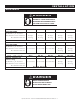
SAFETY PROCEDURES AND PRECAUTIONS Knowledge of proper procedures is essential to the safe operation of electrically and/or gas energized equipment. In accordance with generally accepted product safety labeling guidelines for potential hazards, the following signal words and symbols may be used throughout this manual. DANGER Used to indicate the presence of a hazard that WILL cause severe personal injury, death, or substantial property damage if the warning included with this symbol is ignored.
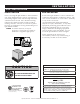
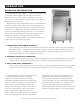
I N S TA L L AT I O N S I T E I N S TA L L AT I O N I N S TA L L AT I O N SITE SELECTION Prior to moving the Quickchiller to the installation site, check the dimensions of doors, passageways, and ceiling heights in the areas through which the cabinet must be moved. Also check the turning radius if the cabinet must be moved around an existing structure. The use of a fork lift or pallet lift truck is required for moving and leveling most Quickchiller models.
I N S TA L L AT I O N S I T E I N S TA L L AT I O N DOOR SEAL: Check the door gasket to make certain it is sealing properly and that the gasket provides an even and positive seal around the entire door frame. I N S TA L L AT I O N R E Q U I R E M E N T S The model QC-3 is a counter mounted unit and must be sealed to the counter with a NSF listed silicone sealant. For all other models, install the appliance on a smooth and level floor surface. Use the adjustable cabinet legs to level the Quickchiller.
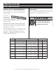
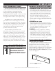
I N S TA L L AT I O N S I T E I N S TA L L AT I O N WAT E R D R A I N A G E DRAINAGE: QC-3 QC-20 QC-40 EVAPORATOR PANS: NO INSTALLATION REQUIRED QC-50 QC-100 ONE (1) FLOOR DRAIN: 1/ 2" (12,7mm) DIAMETER A 1/2" I.D. (12,7mm) PVC pipe is furnished with each QC-50 and QC-100 model. Use PVC glue to attach the pipe into the drain opening at the rear of the unit. Insert the PVC pipe into the drain opening with a 1/4" (6mm) clockwise turn.
I N S TA L L AT I O N ELECTRICAL DANGER ELECTRICAL CONNECTIONS MUST BE MADE BY A QUALIFIED SERVICE TECHNICIAN IN ACCORDANCE WITH APPLICABLE ELECTRICAL CODES. This appliance must be branch circuit protected with proper ampacities, in accordance with the wiring diagram. The Quickchiller must be properly grounded in accordance with the National Electrical Code and applicable local codes.
I N S TA L L AT I O N ELECTRICAL DANGER ELECTRICAL CONNECTIONS MUST BE MADE BY A QUALIFIED SERVICE TECHNICIAN IN ACCORDANCE WITH APPLICABLE ELECTRICAL CODES. VOLTAGE PHASE CYCLE / HZ QC-3 QC-20 QC-40 QC-50 QC-100 30 amps 40 amps 60 amps S E L F - C O N TA I N E D 208-240VAC 1 ph 50/60 Hz R ECOMMENDED CIRCUIT AMPERAGE : R ECOMMENDED WIRE SIZE : 20 amps 12/2 w.g. 20 amps 12/2 w.g. 10/2 w.g. 8/2 w.g. 6/2 w.g.
O P E R AT I O N O P E R AT I N G I N T R O D U C T I O N The Alto-Shaam ® Quickchiller ™ is a processing refrigeration system designed to rapidly and uniformly decrease the temperature of hot foods to either a chilled or frozen state. This process provides enhanced safety, longer storage life and better production efficiency.
O P E R AT I O N CHILL PROCESSING CYCLES The Alto-Shaam Quickchiller uses high velocity cold air circulation to remove heat from prepared foods for the purpose of rapidly reducing temperatures through the danger zone and providing maximum storage life. Cold air is evenly directed across each pan from the control side of every Quickchiller model to assure rapid cooling. The high velocity cold air produced by the Quickchiller removes insulating layers of warm moist air that surrounds hot products.
O P E R AT I O N CAUTION NEVER STACK PANS DIRECTLY ON TOP OF EACH OTHER. STACKED PANS WILL RESTRICT AIR FLOW AND INCREASE CHILL PROCESSING TIME. ➤ Clean the Quickchiller and probes prior to use and make certain all processing modes are operating properly before chilling or freezing foods. ➤ To maintain proper operation of the Quickchiller, always allow the unit to defrost whenever the “DEFROST OVERDUE” warning appears in the display.
O P E R AT I O N “DOOR OPEN” will appear in the display whenever the unit is in operation and the door is opened. When the date and time (only) is showing in the display, this message will not appear when the door is opened. If the Quickchiller door is opened during any running chill or freeze cycle, the fans will disengage and the compressor will cycle down. When the door is closed, the fans and compressor will reengage and the chiller will begin operating at the point of interruption.
O P E R AT I O N C O N T R O L PA N E L I D E N T I F I C AT I O N 쐃 쐇 쐋 쐏 쐄 쐂 쐆 ON / OFF POWER BUTTON . SOFT CHILL … To rapidly decrease the temperature of foods by internal product probe temperature or time within a range of 24°F to 36°F (-4°C to 2°C). Soft Chill is recommended for less dense food items that chill quickly. The mode automatically converts to a refrigerated holding temperature at the end of the chill cycle.
O P E R AT I O N The date and time will appear in the display when the power key is pressed to the OFF position. All operating modes can be initiated when the power key is pressed to the ON position and SELECT: MODE, PRESETS, and PROGRAM appears in the display. To initiate any Quickchiller operating mode, power must initially start from the OFF position or an operating mode must be halted by pressing the S TA R T / S T O P key so that the SELECTION SCREEN appears on the display.
O P E R AT I O N QUICK FREEZE 1. Starting from the OFF press the power key position, ON . 3. The Alto-Shaam name will illuminate and the SELECTION SCREEN will appear on the display. The compressor will become energized and will begin to operate if required by the sensors. 2. 4. Press the QUICK FREEZE key. The display will indicate the last operator set internal compartment temperature.
O P E R AT I O N QUICK FREEZE TIME If time w a s selec ted … The display will indicate the last period of time set by the operator. To change the displayed time, press the right or left arrow keys to select between hours or minutes and the up or down arrow key to increase or decrease the time. Press the START/STOP key. The Display will indicate the last set holding temperature.
O P E R AT I O N HARD CHILL 1. Starting from the OFF press the power key position, ON . 3. The Alto-Shaam name will illuminate and the SELECTION SCREEN will appear on the display. The compressor will become energized and will begin to operate if required by the sensors. 2. 4. Press the HARD CHILL key. The display will indicate the last operator set internal compartment temperature.
O P E R AT I O N HARD CHILL TIME If time w a s selec ted … The display will indicate the last period of time set by the operator. To change the displayed time, press the right or left arrow keys to select between hours or minutes and the up or down arrow key to increase or decrease the time. Press the START/STOP key. The Display will indicate the last set holding temperature.
O P E R AT I O N SOFT CHILL 1. Starting from the OFF press the power key position, ON . 3. The Alto-Shaam name will illuminate and the SELECTION SCREEN will appear on the display. The compressor will become energized and will begin to operate if required by the sensors. 2. 4. Press the SOFT CHILL key. The display will indicate the last operator set internal compartment temperature.
O P E R AT I O N SOFT CHILL TIME If time w a s selec ted … The display will indicate the last period of time set by the operator. To change the displayed time, press the right or left arrow keys to select between hours or minutes and the up or down arrow key to increase or decrease the time. Press the START/STOP key. The Display will indicate the last set holding temperature.
O P E R AT I O N PROGRAMMING TIME If time was selected … Starting from the OFF position, press the power key ON . The Alto-Shaam name will illuminate and the SELECTION SCREEN will appear on the display. The compressor The display will indicate the last period of time set by the operator. To change the displayed time, press the right or left arrow keys to select will become energized and will begin to operate between hours or minutes and the up or down if required by the sensors. 1.
O P E R AT I O N P R E S E T P R O G R A M O P E R AT I O N Starting from the power key ON . OFF position, press the The Alto-Shaam name will 2. Press the up or down arrow keys until the arrow points to the preset menu program desired. illuminate and the SELECTION SCREEN will appear on the display. The compressor will become energized and will begin to operate if required by the sensors. 1. At the SELECTION SCREEN press the 3. Press the START/STOP key.
O P E R AT I O N PROGRAM OPTIONS Starting from the OFF position, press the power key ON . The Alto-Shaam name will illuminate and the SELECTION SCREEN will appear on the display. The compressor will become energized and will begin to operate if required by the sensors. Press the PROGRAM key. The display will indicate all of the following Quickchiller operating parameters each time the Program key is pressed. 1x. 2x.
O P E R AT I O N FOOD PROBE USE Unpacking Food Probes 1. Cut and remove the plastic ties keeping the probe cables coiled during shipment. When removing the ties, exercise caution to avoid accidentally cutting the black plastic covers on the probe cable wires. 2. Uncoil the probe cables and insert the metal portion of each probe into the bracket mounted on the inside of the cabinet. Proper probe placement is in the following sequence: Place the top probe (Product Probe 1) in the top bracket.
O P E R AT I O N FOOD HANDLING GUIDELINES PRODUCT COVERING To maintain sanitation control when loading the Quickchiller, foods should be above 140°F (60°C) and should be tightly covered. A tight cover is an important part of proper chilling methods and must be used to prevent the possibility of accidental contamination by airborne bacteria. Stainless steel pan covers may be used. Stainless steel covered pans must include a label indicating pan contents and use-by date.
O P E R AT I O N Q U I C K C H I L L E R PA N C A PA C I T Y: The following Quickchiller Capacity Chart indicates the number of pans that can be accommodated in the appropriate size chiller for the chilling or freezing function. Additional pans can be accommodated only when using the Quickchiller for holding at a refrigerated temperature or at a maintenance temperature for frozen food. DO N OT OV ERLOA D T H E QUIC K C H ILLER FOR T H E PROC ESSIN G FUN C T ION . CHILLER MODEL QC-3 QC-20 NO .
O P E R AT I O N T H E F O L L O W I N G C H A R T O F P O R T I O N S I Z E S A N D S E R V I N G C A PA C I T Y P E R PA N I S P R O V I D E D A S A G E N E R A L R E F E R E N C E O N LY.
S A N I TAT I O N CLEANING AND PREVENTIVE MAINTENANCE PROTECTING STAINLESS STEEL SURFACES It is important to guard against corrosion in the care of stainless steel surfaces. Harsh, corrosive, or inappropriate chemicals can completely destroy the protective surface layer of stainless steel. Abrasive pads, steel wool, or metal implements will abrade surfaces causing damage to this protective coating and will eventually result in areas of corrosion.
S A N I TAT I O N INTERIOR CLEANING Remove the roll-in cart (trolley) from cart equipped models. Open the quickchiller door to warm the interior of the cabinet. DANGER DISCONNECT UNIT FROM POWER SOURCE BEFORE CLEANING OR SERVICING. 1. Remove any loose food debris with a cleaning cloth or small hand broom. 2. Use a mild, non-abrasive detergent and warm water. Wipe-down the interior of the cabinet, removing all food residue. This includes the ceiling, floor, walls and fan panel.
S A N I TAT I O N EXTERIOR CLEANING 1. 2. Wipe all exterior surfaces including the control panel, door frame, latches, and hinges with a damp cloth containing a mild, non-abrasive, nonchloride detergent solution. Rinse detergent solution with a cloth and warm water. Allow exterior to air dry. DANGER AT NO TIME SHOULD THE INTERIOR OR EXTERIOR BE STEAM CLEANED, HOSED DOWN, OR FLOODED WITH WATER OR LIQUID SOLUTION OF ANY KIND. DO NOT USE WATER JET TO CLEAN. 3.
SERVICE C O N T R O L E R R O R D I S P L AY S CONTROL DISPLAY ACTION REQUIRED Real Time Clock Bad Call service for replacement of defective control. NOTE: Using Default Calibration Values — If the Quickchiller has been unplugged for an extended period of time, the Real Time Clock may only require recharging. Disconnect the unit from the power source. Plug the unit back into the proper receptacle and wait for a minimum of 30 minutes. If the error message remains in the display, repeat this procedure.
SERVICE MODEL: QC-3 CONTROL RM 3 RM 1 RM 2 CIRCUIT BREAKER RELAY RELAY RELAY SW-34152 BA-34021 BA-34009 BA-34010 CONTACTOR PCCC58 FUSE , 15 AMP FU-3775 FUSE BLOCK POWER SUPPLY BOARD FU-3772 BA-33554 Q U I C K C H I L L E R • I N S TA L L AT I O N / O P E R AT I O N / S E R V I C E M A N U A L • 3 1 .
SERVICE MODEL: QC-3 COIL DEFROST AIR SENSOR SN-33541 SIDE RACK , FAN TXV VALVE LEFT- HAND TERMINATOR VA-34216 HEATER PRODUCT PROBE CB-33389 PR-3850 EVAPORATOR COIL CR-33387 EVAPORATOR COIL SENSOR 14285 COIL FAN MOTOR MO-33385 Q U I C K C H I L L E R • I N S TA L L AT I O N / O P E R AT I O N / S E R V I C E M A N U A L • 3 2 .
SERVICE MODEL: QC-20 CONTROL RM 3 RM 1 RM 2 CIRCUIT BREAKER RELAY RELAY RELAY SW-34152 BA-34021 BA-34009 BA-34010 POWER SUPPLY CONTACTOR FUSE , PCCC58 15 AMP FU-3775 FUSE BLOCK FU-3772 BOARD BA-33554 Q U I C K C H I L L E R • I N S TA L L AT I O N / O P E R AT I O N / S E R V I C E M A N U A L • 3 3 .
SERVICE MODEL: QC-20 COIL (2) VA-33972 VA-33932 TXV VALVE AIR SENSOR SN-33541 EVAPORATOR EVAPORATOR DEFROST EVAPORATOR COIL FAN COIL HEATER COIL FAN MOTOR EL-34046 MO-33385 Q U I C K C H I L L E R • I N S TA L L AT I O N / O P E R AT I O N / S E R V I C E M A N U A L • 3 4 .
SERVICE MODEL: QC-20 CONDENSER CONTROL BOX DRAWER CONTROL BOX CONTROL BOX RAIL RAIL PRESSURE SWITCH CONDENSATE PAN ( NOT SHOWN ) Q U I C K C H I L L E R • I N S TA L L AT I O N / O P E R AT I O N / S E R V I C E M A N U A L • 3 5 .
SERVICE MODEL: QC-40 Defrost Heater - CB-34199 Evaporator Coil Coil Sensor - SN-33541 Defrost Terminator Drain Heater - CB-34199 Evaporator Fan Motors - RWEM31 Drain Pan Heater - PN-27799 TXV Valve - RWEV42 Q U I C K C H I L L E R • I N S TA L L AT I O N / O P E R AT I O N / S E R V I C E M A N U A L • 3 6 .
SERVICE MODEL: QC-40 CONTROL POWER SUPPLY BOARD BA-33554 CONTROL BOARD (QC-40/50/100) 5006727 RM 3 RM 2 RELAY RELAY BA-34021 BA-34010 RM 1 RELAY BA-34009 Q U I C K C H I L L E R • I N S TA L L AT I O N / O P E R AT I O N / S E R V I C E M A N U A L • 3 7 .
SERVICE MODEL: QC-50, QC-100 CONTROL POWER SUPPLY BOARD BA-33554 RM 2 RELAY BA-34010 RM 1 RELAY BA-34009 RM 3 RELAY BA-34021 TERMINAL BLOCK Q U I C K C H I L L E R • I N S TA L L AT I O N / O P E R AT I O N / S E R V I C E M A N U A L • 3 8 .
SERVICE MODEL: QC-100 COIL DEFROST TERMINATORS CR-33387 TXV VALVE VA-34128 ( QC -50) RWEV48 ( QC -100) DEFROST HEATERS EL-34268 Q U I C K C H I L L E R • I N S TA L L AT I O N / O P E R AT I O N / S E R V I C E M A N U A L • 3 9 .
SERVICE MODEL: QC-50, QC-100 BREAKER CIRCUIT BREAKER , SW-34153 SW-34154 (QC-100 SW-34153 (QC-100 SW-34152 (QC-100 50 AMP (QC-50) - 208-240V, 1PH) - 208-240V, 3PH) - 380-415V, 3PH) MODEL: QC-50, QC-100 FAN FAN MO-27182 Q U I C K C H I L L E R • I N S TA L L AT I O N / O P E R AT I O N / S E R V I C E M A N U A L • 4 0 .
SERVICE MODEL: QC-50 Remote Coil Sensor Terminal Switches Defrost Heater Drain Heater Cavity Air Sensor Q U I C K C H I L L E R • I N S TA L L AT I O N / O P E R AT I O N / S E R V I C E M A N U A L • 4 1 .
SERVICE MODEL: QC-50, QC-100 REMOTE Remote condensor connection Circuit Breaker Connect wires to condensing unit solenoid here. Low Side Connection High Side Connection Q U I C K C H I L L E R • I N S TA L L AT I O N / O P E R AT I O N / S E R V I C E M A N U A L • 4 2 .
SERVICE MODEL: QC-3 WIRING MODEL: QC-20 WIRING Q U I C K C H I L L E R • I N S TA L L AT I O N / O P E R AT I O N / S E R V I C E M A N U A L • 4 3 .
SERVICE MODEL: QC-40 WIRING Q U I C K C H I L L E R • I N S TA L L AT I O N / O P E R AT I O N / S E R V I C E M A N U A L • 4 4 .
SERVICE MODEL: QC-50 WIRING 1PH 3PH Q U I C K C H I L L E R • I N S TA L L AT I O N / O P E R AT I O N / S E R V I C E M A N U A L • 4 5 .
SERVICE MODEL: QC-100 WIRING 1PH 3PH Q U I C K C H I L L E R • I N S TA L L AT I O N / O P E R AT I O N / S E R V I C E M A N U A L • 4 6 .
TRANSPORTATION DAMAGE and CLAIMS All Alto-Shaam equipment is sold F.O.B. shipping point, and when accepted by the carrier, such shipments become the property of the consignee. Should damage occur in shipment, it is a matter between the carrier and the consignee. In such cases, the carrier is assumed to be responsible for the safe delivery of the merchandise, unless negligence can be established on the part of the shipper. 1. 2. 3. 4. 5. 6. 7. 8.