
Installation Guide


M series - 3 -
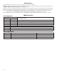
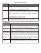
Specifications:
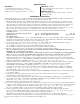
Installation Instructions:
Wiring methods shall be in accordance with the National Electrical Code/NFPA 70/NFPA 72/ANSI, and with all local
codes and authorities having jurisdiction. Product is intended for indoor use only.
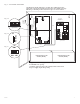
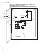
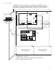
1. Mount unit in the desired location. Mark and predrill holes in the wall to line up with the top two keyholes in the
enclosure. Install two upper fasteners and screws in the wall with the screw heads protruding. Place the enclosure’s
upper keyholes over the two upper screws; level and secure. Mark the position of the lower two holes. Remove the
enclosure. Drill the lower holes and install three fasteners. Place the enclosure’s upper keyholes over the two
upper screws. Install the two lower screws and make sure to tighten all screws (Enclosure Dimensions, pg. 15, 16).
Secure enclosure to earth ground. It is recommended to first review the following tables for screw
terminals, switch selection and LED status indications. This will greatly facilitate installation hook-up.
Carefully review:
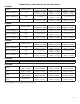
Output Voltage & Stand-by Specifications (pg. 4) Terminal Identification Table (pg. 10)
LED Diagnostics (pg. 9) Typical Application Diagrams (pgs. 11 & 12)
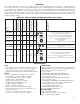
2. Set output voltage:
AL300ULM, AL400ULM (Fig. 1c, pg. 5) and AL600ULM (Fig. 2b, pg. 6) set desired DC output voltage by setting
switch SW1 to the appropriate position on the power supply board. AL1012ULM is 12VDC only. AL1024ULM is
24VDC only. (Output Voltage and Stand-by Specification Charts, pg. 4).
3. Secure green lead to earth ground. Connect AC power (115VAC, 60Hz) to the terminals marked [L, G, N] on
power supply board (Fig. 1, pg. 5; Fig. 2, pg. 6; Fig. 3, pg. 7; Fig. 4, pg. 8).
Use 18 AWG or larger for all power connections (Battery, DC output, AC input).
Use 22 AWG to 18 AWG for power-limited circuits (AC Fail/Low Battery reporting).
4. Measure output voltage before connecting devices. This helps avoiding potential damage.
Keep power-limited wiring separate from non power-limited wiring (115VAC / 60Hz Input, Battery Wires).
Minimum 0.25” spacing must be provided.
CAUTION: Do not touch exposed metal parts. Shut branch circuit power before installing or servicing equipment.
There are no user serviceable parts inside. Refer installation and servicing to qualified service personnel.
For Fire Alarm applications the outputs are “Special Applications” only, see list (refer to Appendix A, pg. 13).
5. Connect Fail-Secure type locking hardware (e.g. door strikes and electronic dead bolts) positive leads to terminals
marked [1 through 5 POS. (+) DC OUTPUT (ALARM)] on MOM5 board and the negative leads to terminals marked
[NEG 1 through NEG 5] on MOM5 board (Fig. 1, pg. 5; Fig. 2, pg. 6; Fig. 3, pg. 7; Fig. 4, pg. 8).
6. Connect Fail-Safe type locking hardware (e.g. mag locks, door strikes and door holders) positive leads to terminals
marked [6 through 10 POS. (+) DC OUTPUT (STAND-BY)] on MOM5 board and negative leads to terminals
marked [NEG 1 through NEG 5] on MOM5 board (Fig. 1, pg. 5; Fig. 2, pg. 6; Fig. 3, pg. 7; Fig. 4, pg. 8).
7. To trigger the unit from a FACP connect signaling circuit of FACP to terminals marked [- INPUT +] on MOM5
board (Fig. 1, pg. 5; Fig. 2, pg. 6; Fig. 3, pg. 7; Fig. 4, pg. 8). Polarity is shown in alarm condition. For latching
fire alarm interface (Fig. 7, pg. 11; Figs. 8 & 9, pg. 12).
Note: A 2.2K EOL must be installed across terminals marked [TRIGGER] on MOM5 board or the unit will remain
in an alarm condition.
8. To trigger the unit using a supervised dry contact connect the 2.2K resistor in series for a NC trigger input
and in parallel for [NO] trigger input (Fig. 5, pg. 11).
9. Connect auxiliary devices triggered by the unit to the terminals marked [DRY OUTPUT NO & C] on MOM5 board
for normally open output or terminals marked [DRY OUTPUT NC & C] on MOM5 board for normally closed
output (Fig. 1, pg. 5; Fig. 2, pg. 6; Fig. 3, pg. 7; Fig. 4, pg. 8).
Note: This relay will energize when the unit is triggered.
10. For Access Control applications batteries are optional. When batteries are not used, a loss of AC will result in the loss
of output voltage. Batteries must be lead acid or gel type if used. Connect one (1) 12VDC battery to terminals marked
[+ BAT -- ] on power supply board for 12VDC operation (Fig. 1, pg. 5; Fig. 2, pg. 6; Fig. 3, pg. 7; Fig. 4, pg. 8).
Use two (2) 12VDC batteries connected in series for 24VDC operation. (Battery leads included).
11. Connect supervisory trouble reporting devices to outputs marked [AC FAIL, LOW BAT] and [Power Fail]
supervisory relay outputs marked [NO, C, NC] on power supply board (Fig. 1a, pg. 5; Fig. 2a, pg. 6; Fig. 3a, pg. 7;
Fig. 4, pg. 8). Use 22 AWG to 18 AWG for AC Fail & Low Battery reporting.
Note: When used in fire alarm, burglar alarm or access control applications, “AC Fail” relay should be
utilized to visually indicate that AC power is on. To delay report for 6 hours cut “AC Delay” jumper (Fig. 1b, pg. 3).
12. Please ensure that the cover is secured with the provided Key Lock.
Supervision:
• AC fail supervision (form “C” contact).
• Low battery supervision (form “C” contact).
• Battery presence supervision (form “C” contact).
Supervision (cont’d):
• Power fail supervision relay (form “C” contact rated
1 amp @ 28VDC).
Additional Features:
• Power supply is complete with enclosure, cam lock,
and battery leads.