M Series Multi-Output Access Control Power Supply Chargers Installation Guide Models Include: • AL300ULM • AL400ULM • AL600ULM • AL1012ULM - 2.5 amp @ 12VDC or 24VDC. - 4 amp @ 12VDC or 3 amp @ 24VDC. - 6 amp @ 12VDC or 24VDC. - 10 amp @ 12VDC. • AL1024ULM - 10 amp @ 24VDC. For a red enclosure, add an “R” suffix to the part # e.g. AL300ULMR Rev.
Overview: These multi-output access control power supply/chargers are specifically designed for use with access control systems and accessories. These units convert a 115VAC, 60Hz input into five (5) individually protected 12VDC or 24VDC outputs (see specifications). Each output will route power to a variety of access control hardware devices including Mag Locks, Electric Strikes, Magnetic Door Holders, etc. These outputs will operate in both Fail-Safe and Fail-Secure modes.
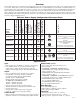
Supervision (cont’d): Specifications: Additional Features: • Power fail supervision relay (form “C” contact rated 1 amp @ 28VDC). • Power supply is complete with enclosure, cam lock, transformer and battery leads. Installation Instructions: Wiring methods shall be in accordance with the National Electrical Code/NFPA 70/NFPA 72/ANSI, and with all local codes and authorities having jurisdiction. Product is intended for indoor use only. 1. Mount unit in desired location.
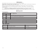
AL300ULM Output Voltage and Stand-by Specification Charts: Switch Position 4 hr. of Stand-by & 5 Minutes of Alarm 12VDC/40AH Battery Closed Stand-by = 2.5 amp Alarm = 2.5 amp Stand-by = 1.0 amp Alarm = 2.5 amp Stand-by = 300mA Alarm = 2.5 amp 24VDC/12AH Battery Open ----------------------------------------- Stand-by = 200mA Alarm = 2.5 amp ----------------------------------------- 24VDC/40AH Battery Open Stand-by = 2.5 amp Alarm = 2.5 amp Stand-by = 1.0 amp Alarm = 2.
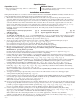
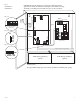
Fig. 1 AL300ULM AL400ULM CAUTION: De-energize unit prior to servicing. For continued protection against risk of electric shock and fire hazard replace fuses with the same type and rating (see marking on the board). Do not expose to rain or moisture. 5A 250V Fig. 1a L Fire Alarm Interface Power Limited AC DC Bat 1 NEG2 NEG3 NEG4 15 SW1 + BAT --- Fig.
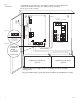
Fig. 2 AL600ULM CAUTION: De-energize unit prior to servicing. For continued protection against risk of electric shock and fire hazard replace fuse with the same type and rating. Do not expose to rain or moisture. 5A 250V Divider Fire Alarm Interface Power Limited L G Wire Strap (from Enclosure to Door) NEG (-) INPUT POS (+) NC C NO NC C NO DRY OUTPUT POWER FAIL AC NEG1 TRIGGER LED SW1 OPEN - 24V CLOSED - 12V + BAT --- OPEN SWITCH 6 7 8 9 10 POS (+) DC OUTPUT (STANDBY) AC FAIL Fig.
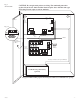
Fig. 3 AL1012ULM CAUTION: De-energize unit prior to servicing. For continued protection against risk of electric shock and fire hazard replace fuses with the same type and rating. Do not expose to rain or moisture. VR1 15 Door Green Lead (ground) BAT FAIL AC FAIL AC DELAY Fig. 3a 5A 250V NC C NO NC C NO NC C NO NC C NO 115VAC power mains non-power limited Class 1 Battery and AC Supervision Circuit (power limited).
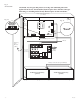
Fig. 4 AL1024ULM CAUTION: De-energize unit prior to servicing. For continued protection against risk of electric shock and fire hazard replace fuses with the same type and rating (see marking on the board). Do not expose to rain or moisture. Battery and AC Supervision Circuit (power limited). Fig. 4a + DC --- Fig.
Maintenance: Unit should be tested at least once a year for the proper operation as follows: Output Voltage Test: Under normal load conditions, the DC output voltage should be checked for proper voltage level (Output Voltage and Stand-by Specification Charts, pg. 4). Battery Test: Under normal load conditions check that the battery is fully charged, check specified voltage at the battery terminals and at the board terminals marked [+ BAT --] to insure that there is no break in the battery connection wires.
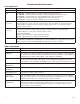
Power Supply Board Terminal Identification Tables: Terminal Legend Function/Description L, G, N Connect 115VAC 60Hz to these terminals: L to hot, N to neutral, G to ground. + DC – AL300ULM - 12VDC/24VDC @ 2.5 amp to MOM5 board (power limited). AL400ULM - 12VDC @ 4 amp or 24VDC @ 3 amp to MOM5 board (power limited). AL600ULM - 12VDC/24VDC @ 6 amp to MOM5 board (non-power limited). AL1012ULM - 12VDC @ 10 amp to MOM5 board (non-power limited). AL1024ULM - 24VDC @ 10 amp to MOM5 board (non-power limited).
Typical Application Diagrams: (-) DC VOLTAGE INPUT FROM FACP SIGNALING OUTPUT OR ACCESS CONTROL DEVICE NEG (-) INPUT POS (+) (+) MOM5 module shown with wet and/or dry normally open trigger inputs (Non-Latching): EOL 2.2K (+) (-) N.C. INPUT FROM FACP OR ACCESS CONTROL DEVICE DC VOLTAGE INPUT FROM FACP SIGNALING OUTPUT OR ACCESS CONTROL DEVICE EOL 2.2K TRIGGER TRIGGER NEG (-) INPUT POS (+) Fig. 5 MOM5 module shown with wet and/or dry normally closed trigger inputs (Non-Latching): N.O.
Typical Application Diagrams (cont’d.): MOM5 module shown with with wet and/or dry normally open fire alarm trigger inputs (Latching with Manual Reset): (+) (-) MOM5 module shown with with wet and/or dry normally closed fire alarm trigger inputs (Latching with Manual Reset): DC VOLTAGE INPUT FROM FACP SIGNALING OUTPUT NEG (-) INPUT POS (+) NEG (-) INPUT POS (+) Fig. 8 (-) DC VOLTAGE INPUT FROM FACP SIGNALING OUTPUT TRIGGER TRIGGER EOL 2.2K (+) N.O.
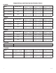
Appendix A - UL Listed Compatible Devices A.1 Four (4) Wire Smoke Detectors Table A-1 below lists four (4) wire smoke detectors compatible with AL300ULM, AL400ULM, AL600ULM, AL1012ULM & AL1024ULM output.
AL1024ULM Battery size calculation worksheet. A. AL1024ULM internal current consumption (standby) ________________ .13 A B. Load current consumption (standby) ________________ A C. Standby time required (hours) ________________ H D. Battery capacity required for standby (A+B)*C ________________ AH E. AL1024ULM internal power consumption (Alarm) ________________ .13 A F. Load current consumption (Alarm) ________________ A G. Alarm duration (Hours, example:15 Min=.
Enclosure Dimensions (BC300): AL300ULM, AL400ULM and AL600ULM 13.5” (342.9mm) x 13” (330.2mm) x 3.25” (82.55mm) 1.40” (36mm) 4.85” (123mm) 4.85” (123mm) 1.40” (36mm) 1.20” (31mm) 3.25” (83mm) 1.20” (31mm) 0.75” (19mm) 12.5” (318mm) 11.0” (279mm) 1.20” (31mm) 0.75” (19mm) 0.9375” (24mm) 1.40” (36mm) 1.40” (36mm) 5.10” (130mm) 5.10” (130mm) 13.0” (330mm) 5.10” (130mm) 6.5625” (167mm) 0.9375” (24mm) 3.25” (83mm) 3.25” (83mm) 3.25” (83mm) 1.0” (25mm) 1.0” (25mm) 1.0” (25mm) M series 10.
Enclosure Dimensions (BC400): AL1012ULM and AL1024ULM 15.5” (393.7mm) x 12” (304.8mm) x 4.5” (114.3mm) 1.5” (38.1mm) 4.615” (117.22mm) 4.615” (117.22mm) 1.5” (38.1mm) 1.75” (44.45mm) 1.375” (34.925mm) 1.125” (28.575mm) 1.25” (31.75mm) 4.5” (114.3mm) 12.23” (310.64mm) 1.1” (27.94mm) 0.91” (23.114mm) 1.5” (38.1mm) 4.5” (114.3mm) 1.1” (27.94mm) 1.25” (31.75mm) 0.91” (23.114mm) 2.0” (50.8mm) 1.5” (38.1mm) 15.5” (393.7mm) 2.0” (50.8mm) 5.0” (127.0mm) 5.0” (127.0mm) 1.1” (27.94mm) 1.