
Installation Guide


- 2 - ALTV1224DC220 Series Installation Guide
Installation Instructions:
1. Mount unit in the desired location. Mark and predrill holes in the wall to line up with the top two keyholes
in the enclosure. Install two upper fasteners and screws in the wall with the screw heads protruding. Place
the enclosure’s upper keyholes over the two upper screws; level and secure. Mark the position of the lower
two holes. Remove the enclosure. Drill the lower holes and install two fasteners. Place the enclosure’s
upper keyholes over the two upper screws. Install the two lower screws and make sure to tighten all screws
(Enclosure Dimensions, pg. 8). Secure enclosure to earth ground.
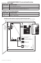
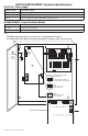
2. Slide switch to OFF position (Fig. 1, pg. 3, Fig. 2, pg. 4 or Fig. 3, pg. 5).
3. Set the unit to desired DC output voltage range by setting switch (SW1) on the power supply board to the
appropriate position. Use trimpot to adjust voltage if necessary (Fig. 1, pg. 3, Fig. 2, pg. 4 or Fig. 3, pg. 5).
4. Connect AC circuit (220VAC, 50/60Hz) as follows: Green branch wire connects to earth (safety) ground
lug . Line and Neutral to the connector on power supply board marked [L, N] respectively
(Fig. 1, pg. 3, Fig. 2, pg. 4 or Fig. 3, pg. 5).
5. Measure output voltage before connecting devices. This helps avoiding potential damage.
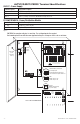
6. Connect each DC device to the output terminals 1 through 8 (Fig. 1, pg. 3) or terminals 1 through 16
(Fig. 2, pg. 4 or Fig. 3, pg. 5).
Note: Be careful to observe camera polarity.
7. When batteries are being used, the DC output voltage must be adjusted by turning the trim pot VR1
(Fig. 1, pg. 3, Fig. 2, pg. 4 or Fig. 3, pg. 5) clockwise to increase the output voltage to 13.7VDC for
12VDC operation and 27.1VDC for 24VDC operation.
Connect battery to theterminals marked [– BAT +] (battery leads included) (Fig. 1, pg. 3, Fig. 2, pg. 4 or
Fig. 3, pg. 5). Use two (2) 12VDC batteries connected in series for 24VDC operation.
8. Slide switch to ON position (Fig. 1, pg. 3, Fig. 2, pg. 4 or Fig. 3, pg. 5).
9. Green LED on the PD8/PD8CB or PD16W/PD16WCB board will illuminate when power is present.
10. Upon completion of the wiring, secure enclosure door with screws (supplied).
Input:
• Input 220VAC (working range 198VAC-256VAC),
50/60 Hz.
Output:
• Eight (8) or sixteen (16) fuse or
PTC protected outputs.
• 12VDC or 24VDC.
• Outputs are rated @ 3.5A (fused) or 2.5A (PTC).
• Filtered and electronically regulated outputs.
Features:
• AC input and DC output LED indicators.
• Power ON/OFF switch.
• Unit maintains camera synchronization.
• Ease of installation saves time and eliminates
costly labor.
Enclosure Dimensions (H x W x D approx.):
13.5” x 13” x 3.25”
(342.9mm x 330.2mm x 82.6mm).
Door
CAUTION: De-energize unit prior to servicing. For continued protection against
fire hazard replace fuse with the same type and rating. Do not expose unit to rain or moisture.
N
COMMON POWER OUTPUTS
P
FUSED POWER OUTPUTS
1 2 3 4 5 6 7 8
D1
INPUT
R1
LED
Wire Strap
(from
Enclosure
to Door)
220VAC
power
mains
Divider
Switch disables power mains
line voltage input.
If stand-by battery (batteries) are
connected the DC output remains on.
OFF ON
Trimpot
Adjusts output voltage
on power supply
SW1
24VDC output - OFF
12VDC output - ON
OFF - 24V
ON - 12V
ON
OFF - 24V
ON - 12V
ON
Ground
Lug
Used on ALTV1224DCCB220
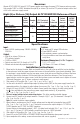
Overview:
Altronix ALTV1224DC220 Series DC CCTV power supplies are designed to power CCTV Cameras and accessories.
Units provide 12VDC or 24VDC distributed via eight (8) or sixteen (16) fused or PTC protected outputs with a total
of 4A or 6A continuous supply current.
Eight (8) or Sixteen (16) Output ALTV1224DC220 Reference Chart:
Altronix
Model Number
Total
Output
Current
(Power)
Number
of
Outputs
PTC Protected
Auto-Resettable
Outputs
Fuse
Protected
Outputs
Output
Current
(max per
output)
220VAC
50/60Hz
Input
Current
ALTV1224DC220
4A
8
–
P
3.5A
0.9A
ALTV1224DCCB220
P
– 2.5A
ALTV1224DC1220
16
–
P
3.5A
ALTV1224DC1CB220
P
– 2.5A
ALTV1224DC2220
6A
–
P
3.5A
1.5A
ALTV1224DC2CB220
P
– 2.5A
Specifications: