
Installation Guide

eFlow104N Series - 3 -
Specifications:
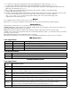
Installation Instructions:
Wiring methods shall be in accordance with the National Electrical Code/NFPA 70/NFPA 72/ANSI, The Canadian Elec-
trical Code, Part 1 and with all local codes and authorities having jurisdiction. Product is intended for indoor use only.
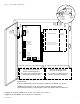
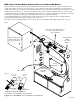
1. Mount unit in desired location. Mark and predrill holes in the wall to line up with the top two keyholes in the
enclosure. Install two upper fasteners and screws in the wall with the screw heads protruding. Place the enclosure’s
upper keyholes over the two upper screws, level and secure. Mark the position of the lower two holes. Remove the
enclosure. Drill the lower holes and install the two fasteners. Place the enclosure’s upper keyholes over the two
upper screws. Install the two lower screws and make sure to tighten all screws (Enclosure Dimensions, pgs. 11-12).
Secure enclosure to earth ground.
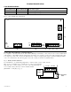
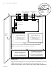
2. Connect unswitched AC power (120VAC 60Hz) to terminals marked [L, N] (Fig. 1a, pg. 5). Use 14 AWG or
larger for all power connections. Secure green wire lead to earth ground.
Keep power-limited wiring separate from non power-limited wiring (120VAC 60Hz Input, Battery Wires).
Minimum 0.25” spacing must be provided.
CAUTION: Do not touch exposed metal parts. Shut branch circuit power before installing or servicing equipment.
There are no user serviceable parts inside. Refer installation and servicing to qualified service personnel.
For Fire Alarm applications the outputs are “Special Applications” only, see list (refer to Appendix A, pg. 12).
3. Measure output voltage before connecting devices. This helps avoiding potential damage.
4. Connect devices to be powered:
a. For eFlow104N/eFlow104NX connect devices to terminals marked [- DC +] (Fig. 1h, pg. 3).
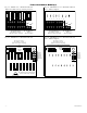
b. For other Power Distribution Models connect devices to be powered to terminal pairs 1 to 8 marked
[1P & 1N] through [8P & 8N] (Fig. 3a & 3b, pg. 6) or 1 to 16 marked [1P & 1N] through [16P & 16N]
(Fig. 4a & 4b, pg. 6) carefully observing correct polarity.
For auxiliary device connection this output will not be affected by Low Power Disconnect or Fire Alarm Interface.
Connect device to terminals marked [+ AUX -- ] (Fig. 1f, pg. 5).
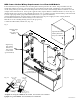
5. For Access Control applications batteries are optional. When batteries are not used, a loss of AC will result in the loss
of output voltage. When the use of stand-by batteries is desired, they must be lead acid or gel type.
Connect battery to terminals marked [-- BAT + ] (Fig. 1g, pg. 5). Use two (2) 12VDC batteries connected in series for
24VDC operation (battery leads included). Use batteries - Casil CL1270 (12V/7AH), CL12120 (12V/12AH),
CL12400 (12V/40AH), CL12650 (12V/65AH) batteries or UL recognized BAZR2 batteries of an appropriate rating.
6. Connect appropriate signaling notification devices to AC FAIL & BAT FAIL (Fig. 1b, pg. 5) supervisory
relay outputs.
7. To delay AC reporting for 2 hrs. set dip switch [AC Delay] to OFF position (Fig. 1c, pg. 5).
To delay AC reporting for 1 min. set dip switch [AC Delay] to ON position (Fig. 1c, pg. 5).
Note: Must be set to ON position for Burglar Alarm Applications.
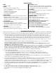
Input:
• 120VAC,60Hz.
Output:
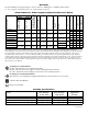
• Foroutputvoltageandsupplycurrent,
refer to eFlow104N series Power Supply Configuration
Reference Chart, pg. 2.
• AuxiliaryPower-Limitedoutput
rated @ 1 amp (unswitched).
• OverVoltageProtection.
Battery Backup:
• Built-inchargerforsealedleadacidorgeltypebatteries.
• Maximumchargecurrent1.54amp.
• Automaticswitchovertostand-bybatterywhenACfails.
Transfer to stand-by battery power is instantaneous with
no interruption.
Fire Alarm Disconnect:
• SupervisedFireAlarmdisconnect(latchingor
non-latching) 10K EOL resistor. Operates on a normally
open (NO) or normally closed (NC) trigger.
Supervision:
• ACfailsupervision(form“C”contacts).
• Batteryfail&presencesupervision(form“C”contacts).
Supervision (cont’d):
• Lowpowershutdown.ShutsdownDCoutputterminals
if battery voltage drops below 70-75% (depending on the
power supply). Prevents deep battery discharge.
Fuse Ratings:
• RefertoeFlow104NSeriesPowerSupplyConfiguration
Reference Chart, pg. 2.
Visual Indicators:
• GreenACPowerLEDindicates120VACpresent.
• ACinputandDCoutputLEDindicators.
Additional Features:
• Shortcircuitandoverloadprotection.
• Unitiscompletewithpowersupply,enclosure,
battery leads and cam lock.
Enclosure Dimensions (approximate H x W x D):
eFlow104N, eFlow104N8, eFlow104N8D,
eFlow104N16, eFlow104N16D:
13.5” x 13” x 3.25” (342.9mm x 330.2mm x 82.55mm)
eFlow104NX, eFlow104NX8, eFlow104NX8D,
eFlow104NX16, eFlow104NX16D:
15.5” x 12” x 4.5” (393.7mm x 304.8mm x 114.3mm)