
Installation Guide

- 4 - eFlow104N Series
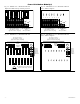
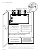
8. To enable Low Output Power Shutdown set dip switch [Shutdown] to ON position (Fig. 1c, pg. 5).
To disable Low Output Power Shutdown set dip switch [Shutdown] to OFF position (Fig. 1c, pg. 5).
9. Trigger terminals are end of a line resistor supervised (10k ohms). Opening or shorting trigger terminals will cause
[DC] output to shutdown (Fig. 1d, pg. 5).
10. Place a jumper for non-latching FACP. A momentary short on these terminals resets FACP latching
[Trigger EOL Shutdown] (Fig. 1e, pg. 5).
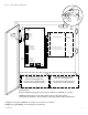
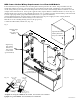
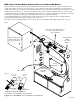
11. For Access Control Applications: mount UL Listed tamper switch (Sentrol model 3012 or equivalent) at the top of the
enclosure. Slide tamper switch bracket onto the edge or the enclosure approx. 2” from the right side
(Fig. 5, pg. 7 or Fig. 7, pg. 9). Connect tamper switch wiring to the Access Control Panel input or the
appropriate UL Listed reporting device.
Wiring:
Use 18 AWG or larger for all low voltage power connections.
Note: Take care to keep power-limited circuits separate from non power-limited wiring (120VAC, Battery).
Maintenance:
Unit should be tested at least once a year for the proper operation as follows:
Output Voltage Test: Under normal load conditions, the DC output voltage should be checked for proper voltage level
eFlow104N: 24VDC nominal rated @ 10 amp max.
Battery Test: Under normal load conditions check that the battery is fully charged, check specified voltage
(24VDC @ 26.4) both at battery terminal and at the board terminals marked [-- BAT + ] to ensure that there is no break in
the battery connection wires.
Note: Maximum charging current under discharges is 1.54 amp.
Note: Expected battery life is 5 years, however it is recommended changing batteries in 4 years or less if needed.
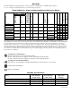
LED Diagnostics:
Power Supply/Charger
Red (DC) Green (AC/AC1) Power Supply Status
ON ON Normal operating condition.
ON OFF Loss of AC, Stand-by battery supplying power.
OFF ON No DC output.
OFF OFF Loss of AC. Discharged or no stand-by battery. No DC output.
Power Distribution Module
Green (AC) Power Distribution Module Status
ON Normal operating condition.
OFF No Power Output.
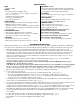
Terminal Identification:
Power Supply/Charger
Terminal
Legend
Function/Description
L, N Connect 120VAC 60Hz to these terminals: L to hot, N to neutral (non power-limited) (Fig. 1a, pg.5).
– DC + 24VDC nominal @ 10 amp continuous output (non power-limited output) (Fig. 1h, pg. 5).
Trigger EOL
Supervised
Fire Alarm Interface trigger input from a short or FACP. Trigger inputs can be normally open,
normally closed from an FACP output circuit (power-limited input) (Fig. 1d, pg. 5).
NO, GND
RESET
FACP interface latching or non-latching (power-limited) (Fig. 1e, pg. 5).
+ AUX – Auxiliary Power-Limited output rated @ 1 amp (unswitched) (power-limited output) (Fig. 1f, pg. 5).
AC Fail
NC, C, NO
Indicates loss of AC power, e.g. connect to audible device or alarm panel. Relay normally energized
when AC power is present. Contact rating 1 amp @ 30VDC (power-limited) (Fig. 1b, pg. 5).
Bat Fail
NC, C, NO
Indicates low battery condition, e.g. connect to alarm panel. Relay normally energized when DC power
is present. Contact rating 1 amp @ 30VDC. A removed battery is reported within 5 minutes.
Battery reconnection is reported within 1 minute (power-limited) (Fig. 1b, pg. 5).
– BAT + Stand-by battery connections. Maximum charge current 1.54 amp (non power-limited) (Fig. 1g, pg. 5).