
HubSat4D Installation

- 2 - HubSat4D
Overview:
Altronix HubSat4D Passive UTP Transceiver Hub w/Integral Camera Power transmits UTP video, RS422/RS485 data and
power over a single CAT-5 or higher structured cable. Unit provides 4 camera channels in a wall mount enclosure. Video
transmission range is up to 750 ft. max. per channel. Units are compatible with AC and/or DC fixed or PTZ cameras when
utilizing Altronix HubWayAv or HubWayDv Video Balun/Combiners. In addition, the unit features individually selectable
24VAC or 28VAC PTC protected outputs with surge suppression. Optionally, the HubSat4D can be used as an accessory
module to transmit video from up to 4 cameras over a single CAT-5 or higher structured cable back to the HubWay,
HubWayLD or HubWayLDH Passive and Active UTP Transceiver Hubs. In addition, the HubSat4D provides power to
these cameras locally to eliminate the possibility of voltage drop associated with long cable runs.
Input:
• 115VAC 50/60Hz, .9 amp.
• Primary in-line fuse is rated @ 3.5A/250V.
Video:
• Four (4) channels of quality video over twisted pair
up to a distance of 750 ft. per channel.
• Four (4) 75 ohm video outputs.
Data:
• RS422/RS485 data input.
Power:
• Individually selectable 24VAC or 28VAC power
outputs with OFF position.
• PTC protected outputs.
• PTCs are rated @ 1 amp per channel.
Power (cont.):
• Unit provides up to 1 amp max. per channel not to
exceed a total of 4 amp maximum current.
• Surge suppression.
Visual Indicators:
• Four (4) power LED indicators.
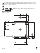
Enclosure Dimensions:
8.5”H x 7.5”W x 3.5”D
Optional Accessories:
• Video Balun/Combiners:
- HubWayAv - for use with 24VAC cameras.
- HubWayDv - for use with 12VDC cameras.
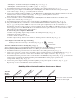
Specifications:
Additional Models:
HubSat42D
• HubSat4D w/four (4) HubWayAv Video Balun/
Combiners for 24VAC Cameras.
HubSat43D
• HubSat4D w/four (4) HubWayDv Video Balun/
Combiners for 12VDC Cameras.
Installation Instructions:
HubSat4D Passive UTP Transceiver Hub with Integral Camera Power.
1. Mount unit in desired location. Mark and predrill holes in the w
all to line up with the top two keyholes in the
enclosure. Install two upper fasteners and screws in the wall with the screw heads protruding. Place the enclosure’s
upper keyholes over the two upper screws, level and secure. Mark the position of the lower two holes. Remove the
enclosure. Drill the lower holes and install the two fasteners. Place the enclosure’s upper keyholes over the two
upper screws. Install the two lower screws and make sure to tighten all screws (Enclosure Dimensions, pg. 8).
Secure green wire lead to earth ground.
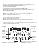
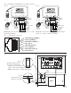
2. Set illuminated master power disconnect circuit breaker to the (OFF) position (Fig. 4a, pg. 6).
3.
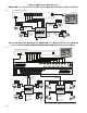
Connect 115VAC 50/60Hz to the black and white flying leads of open frame transformer. Secure ground
wire (Green) to earth ground (Fig. 5, pg. 7). The power LEDs (Green) for Channels 1-4 of the HubSat4D
will illuminate when
AC power is present (Fig
. 1e, pg. 4)
4. Select 24VAC or 28VAC power output for Channels 1-4 with the corresponding voltage adjustment switches
(Fig. 1d, pg. 4).
5. Connect the BNC video outputs for HubSat4D Channels 1 - 4 to the corresponding video inputs
on the head end equipment (D
VR) (Fig. 1a, pg. 4).
6. Connect the RS422/RS485 output of the head end equipment (DVR) to the data ter
minals marked [+ Data ---]
of the HubSat4D unit (polarity must be observed) (Fig. 1f, pg. 4).
Note: The Data input terminals of the HubSat4D must be wired in parallel for proper operation.
When using f
ixed cameras disregard this step.