
HubSat4D Installation

HubSat4D - 3 -
7. Connect Video Balun/Combiner at camera 1 to the HubSat4D unit utilizing CAT-5 or higher structured cable.
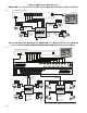
Plug the RJ45 connector at one end of a structured cable into the RJ45 jack marked [PVD1] of the
HubSat4D (F
ig. 1i, pg. 4). Plug the RJ45 connector at the opposite end of the structured cable into the
RJ45 jack of the Video Balun/Combiner located at camera 1.
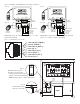
• For 24VAC cameras use Altronix model HubWayAv Video Balun/Combiner (Figs. 2a, 2b, pg. 6).
•
For 12VDC cameras use Altronix model HubWayDv Video Balun/Combiner (Figs. 2c, 2d, pg. 6).
A
C LED (Green) of the HubWayAv or DC LED (Red) of the HubWayDv Video Balun/Combiners will illuminate
indicating power is present at the cameras (Fig. 2b, 2d, pg. 6).
The total cable distance must not exceed 750 ft. for video transmission between the HubSat4D and each camera.
Repeat this step for each additional camera [PVD2-4].
8.
Set illuminated master power disconnect circuit breaker to the RESET (ON) position (Fig. 4a, pg. 6) and
measure the output v
oltage at the power output of each Video Balun/Combiner (Figs. 2b, 2d, pg. 6) before
po
wering each camera to insure proper operation and avoid possible damage.
• HubWayAv - Terminals marked [AC POWER] (Figs. 2a, 2b, pg. 6).
•
HubWayDv - Terminals marked [– 12VDC +] (Figs. 2c, 2d, pg. 6).
9.
Set illuminated master power disconnect circuit breaker to the (OFF) position (Fig. 4a, pg. 6).
10.
Connect the power outputs of the HubWayAv or HubWayDv Video Balun/Combiners to the power inputs
of the cameras (Figs. 2a-2d, pg. 6). Polarity must be observed.
11.
Connect the terminals marked [+ DATA -- ] of the HubWayAv or HubWayDv Video Balun/Combiners to the data
terminals of the cameras for PTZ control (Figs. 2b-2d, pg. 6). Polarity must be observed. When using fixed cameras
disre
gard this step.
12. Connect the BNC connector of the HubWayAv or HubWayDv Video Balun/Combiners to the BNC video
outputs of the cameras (Figs. 2b-2d, pg. 6).
13. Set illuminated master pow
er disconnect circuit breaker to the RESET (ON) position (Fig. 4a, pg
. 6).
14. The power LEDs (Green) or Channels 1-4 of the HubSat4D will illuminate when AC power is present
(Fig. 1e, pg. 4). If any of these LEDs are off, a loss of AC power output may be due to a tripped PTC caused
b
y a short circuit or overload condition. If all of the LEDs are OFF there may be a complete loss of supply power to
the HubSat4D unit or the illuminated master power disconnect circuit breaker is in the OFF position or the primary
in-line fuse is blown.*
To restore the power output for HubSat4D:
1- Switch cor
responding output voltage switch to the OFF position (Fig. 1d, pg. 4).
2- Eliminate the trouble condition.
3- Allow 1 minute for PTC to cool off.
4- Switch output voltage switch to the 24VAC or 28VAC position as desired (Fig. 1d, pg. 4).
*Note: Replace fuse with same type and r
ating:
Primary in-line fuse is rated @ 3.5A/250V (Fig. 4b, pg. 6).
HubSat4D for use as a Remote
Accessory Module with HubWay/HubWayLD/HubWayLDH UTP Transceiver Hubs.
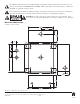
1. Mount unit in desired location. Mark and predrill holes in the wall to line up with the top two keyholes in the
enclosure. Install tw
o upper fasteners and screws in the wall with the screw heads protruding. Place the enclosure’s
upper keyholes over the two upper screws, level and secure. Mark the position of the lower two holes. Remove the
enclosure. Drill the lower holes and install the two fasteners. Place the enclosure’s upper keyholes over the two
upper screws. Install the two lower screws and make sure to tighten all screws (Enclosure Dimensions, pg. 8).
Secure g
reen wire lead to earth ground.
2. Set illuminated master power disconnect circuit breaker to the (OFF) position (Fig. 4a, pg
. 6).
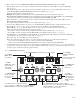
3. Connect 115VAC 50/60Hz to the black and white flying leads of open frame transformer. Secure ground
wire (Green) to earth ground (Fig. 6, pg. 7). The power LEDs (Green) for Channels 1-4 of the HubSat4D will
illuminate w
hen AC power is present (Fig. 1e, pg. 4).
4. Select 24V
AC or 28VAC power output for Channels 1-4 with the corresponding voltage adjustment switches
(Fig. 1d, pg. 4).
5.
Video connection between HubSat4D and HubWay/HubWayLD/HubWayLDH:
Plug the RJ45 connector at one end of a structured cable into the RJ45 jack marked [Video 1-4] of the HubSat4D
(Fig. 1g, pg. 4).
Plug the RJ45 connector at the opposite end of the structured cab
le into the RJ45 jack marked [Channels 1-4,
Channels 5-8, Channels 9-12, Channels 13-16] of the HubWay/HubWayLD/HubWayLDH (Fig. 6, pg. 7).
Primary
In-line Fuse