
HubSat4D Installation

- 4 - HubSat4D
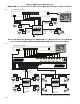
6. Data connection between HubSat4D and HubWay/HubWayLD/HubWayLDH UTP Transceiver Hubs:
Plug the RJ45 connector at one end of a structured cable into the RJ45 jack marked [Data 1-4] of the HubSat4D
(F
ig. 1h, pg. 4).
Plug the RJ45 connector at the opposite end of the structured cable into the corresponding RJ45 channel jack
of the HubWay/HubWayLD/HubWayLDH UTP Transceiver Hubs (Fig. 6, pg. 7).
When using f
ixed cameras disregard this step.
Example: Using RJ45 jack marked [Video 1-4] of HubSat4D connected to [Channels 1-4] of the
HubW
ay/HubWayLD/HubWayLDH for video transmission, Using the RJ45 jack marked [Data 1-4] of HubSat4D
connected to the Channel jack marked [4] of the HubWay/HubWayLD/HubWayLDH.
Note: Channels 1-3 can not be used for video transmission when using the RJ45 jack marked [CH 1-4] of the
HubW
ay/HubWayLD/HubWayLDH.
The output voltage switches 1-4 must be set to OFF position (Fig. 6, pg. 7).
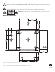
7. Connect Video Balun/Combiner at camera 1 to the HubSat4D unit utilizing CAT-5 or higher structured cable.
Plug the RJ45 connector at one end of a str
uctured cable into the RJ45 jack marked [PVD1] of the
HubSat4D (Fig. 1e, pg. 4). Plug the RJ45 connector at the opposite end of the structured cable into the
RJ45 jack of the
Video Balun/Combiner located at camera 1.
• For 24VAC cameras use Altronix model HubWayAv Video Balun/Combiner (Figs. 2a, 2b, pg. 6).
•
For 12VDC cameras use Altronix model HubWayDv Video Balun/Combiner (Figs. 2c, 2d, pg. 6).
A
C LED (Green) of the HubWayAv or DC LED (Red) of the HubWayDv Video Balun/Combiners will illuminate
indicating power is present at the cameras (Fig. 2b, 2d, pg. 6).
Repeat this step for each additional camera [OUT2-4].
Note: The combined total cable distance for video transmission must not exceed the following distances:
-
750 ft. between the HubWay and each camera routed through the HubSat4D.
- 3000 ft. between the HubWayLD/HubWayLDH and each camera routed through the HubSat4D.
8. Set illuminated master power disconnect circuit breaker to the RESET (ON) position (Fig. 4, pg. 6) and measure the
output v
oltage at the power output of each Video Balun/Combiner (Figs. 2b, 2d, pg. 6) before powering each camera
to insure proper operation and a
void possible damage.
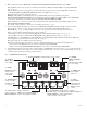
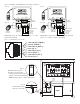
Fig. 1 - HubSat4D Circuit Board
1i - Channels 1-4:
CAT
-5 or higher
structured cable
to cameras.
PVD1
VIDEO1 VIDEO2 VIDEO3 VIDEO4
PVD2 PVD3 PVD4
+ DATA -
DATA 1-4 VIDEO 1-4
28VAC
24VAC
28VAC
24VAC
28VAC
24VAC
28VAC
24VAC
OFF
OFF
OFF
OFF
AUX1 AUX2 AUX3 AUX4
1d - Output
Voltage Switches:
Selects
24V
AC/28VAC/OFF
for each output.
1e - LED(s) 1-4:
Power output
indicators.
1a - BNC
Connector: Video
in from remote
camera video
out to D
VR.
1g - Channels 1-4: Single CAT-5 or higher
structured cable out to HubWay8/16, HubWayLD8/16,
HubWayLDH8/16 enables transmission
of up to four (4) video signals.
1h - Data: CAT-5 or higher structured
cable to data port on HubWay8/16, HubWayLD8/16,
HubWayLDH8/16 or head end equipment (DVR).
1c - Power Terminals: 24VAC/28VAC power outputs.
1b - Output
PTCs: Protects
each output.
1f - Data:
RS422/RS485
input from head
end equipment
(D
VR) for PTZ
control.