
HubSat4D Installation

HubSat4D - 5 -
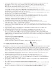
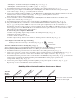
HubWayAv
*24VAC/28VAC *24VAC/28VAC
Use with AC cameras
Green
HubWayDv
12VDC *24VAC/28VAC
Use with DC cameras
Red
Altronix
Model
Number
HubWay Video Balun/Combiner Reference Chart:
Output Voltage
to camera
Input Voltage
from HubSat
Camera Type
Power LED
*Based on camera load and
structured cable length.
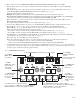
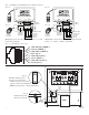
• HubWayAv - Terminals marked [AC POWER] (Figs. 2a, 2b, pg. 6).
• HubW
ayDv - Terminals marked [– 12VDC +] (F
igs. 2c, 2d, pg. 6).
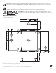
9. Set illuminated master power disconnect circuit breaker to the (OFF) position (F
ig. 4a, pg. 6).
10. Connect the power outputs of the HubWayAv or HubWayDv Video Balun/Combiners to the power inputs
of the cameras (Figs. 2a-2d, pg. 5). Polarity must be observed.
11.
Connect the terminals marked [+ DATA -- ] of the HubWayAv or HubWayDv Video Balun/Combiners to the data
terminals of the cameras for PTZ control (Figs. 2a-2d, pg. 5). Polarity must be observed.
When using fixed cameras disregard this step.
12.
Connect the BNC connector of the HubWayAv or HubWayDv Video Balun/Combiners to the BNC video
outputs of the cameras (Figs. 2b-2d, pg. 6).
13.
Set illuminated master power disconnect circuit breaker to the RESET (ON) position (Fig. 4a, pg. 6).
14. The power LEDs (Green) or Channels 1-4 of the HubSat4D will illuminate when AC power is present
(Fig. 1e, pg. 4). If any of these LEDs are off, a loss of AC power output may be due to a blown fuse or a
tripped PTC caused b
y a short circuit or overload condition. If all of the LEDs are OFF there may be a complete
loss of supply power to the HubSat4D unit or the illuminated master power disconnect circuit breaker is in the
OFF position or the primary in-line fuse is blown.*
To restore the power output for HubSat4D:
1- Switch corresponding output voltage switch to the OFF position (Fig. 1d, pg. 4).
2-
Eliminate the trouble condition.
3- Allow 1 minute for PTC to cool off.
4- Switch output voltage switch to the 24VAC or 28VAC position as desired (Fig. 1d, pg. 4).
*Note: Replace fuse with same type and rating:
Primary in-line fuse is rated @ 3.5A/250V (Fig. 4b, pg
. 6).
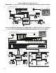
Alternate 24VAC fixed camera hookup (Fig. 6a, pg. 7).
After completing steps 1-5 from Installation Instructions Remote Accessory Module for use with
HubWay/HubWayLD/HubWayLDH UTP Transceiver Hubs proceed with the follo
wing.
1. Set illuminated master power disconnect circuit breaker to the (OFF) position (Fig. 4a, pg. 6).
2.
Connect one end of the coaxial cable to the BNC connector marked [Video1] of the HubSat4D (Fig. 1a, pg. 4).
Connect the opposite end of the coaxial cable to the BNC video output of camera 1 (Fig
. 6a, pg. 7).
3. Set illuminated master power disconnect circuit breaker to the RESET (ON) position (Fig. 4a, pg. 6) measure the
output v
oltage at terminal pair marked [AUX1] of the HubSat4D to insure proper operation and
avoid possible damage (Fig. 1b, pg. 4).
4.
Connect the power output terminal pair marked [AUX1] to the power inputs of camera 1 (Fig. 1c, pg. 4).
Repeat steps 1-3 for each additional camera (Channels 2-4).
Primary
In-line Fuse