
Installation

HubWay Passive Unit - 3 -
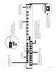
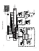
7. Connect the BNC video outputs for HubWay8DS Channels 1-8 to the corresponding video inputs on the head end
equipment (DVR) (F
ig. 1d, pg. 4).
8. Connect the RS422/RS485 output of the head end equipment (DVR) to the data input terminal block of
the HubWay8DS unit (polarity must be observed) (F
ig. 1c, pg. 4).
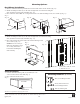
9. Connect Video Balun/Combiner at camera 1 to the HubWay8DS unit utilizing CAT-5 or higher structured cable.
Plug the RJ45 connector at one end of the structured cable into the RJ45 jack marked [Channel 1] of the
HubWay8DS (Fig. 1g, pg. 4). Plug the RJ45 connector at the opposite end of the structured cable into the
RJ45 jack of the
Video Balun/Combiner located at camera 1.
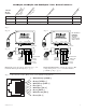
• For 24VAC cameras use Altronix model HubWayAv Video Balun/Combiner (Figs. 2a, 2b, pg. 5).
•
For 12VDC cameras use Altronix model HubWayDv Video Balun/Combiner (Figs. 2c, 2d, pg. 5).
•
For non-isolated 12VDC cameras use Altronix model HubWayDvi Video Balun/Combiner (Figs. 2c, 2d, pg. 5).
Repeat steps 6-9 for each additional camera (Channels 2-8).
Note: When a particular camera exceeds the maximum distance for power transmission, a local
e
xternal power source is required. Optionally, an Altronix HubSat Passive UTP Transceiver Hub with Integral
Camera Power unit may be utilized (Fig. 4a, pg. 6). The combined total cable distance must not exceed 750 ft.
for video transmission betw
een the HubWay8DS and each camera routed through the HubSat4D unit.
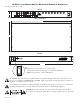
10. Set illuminated master power disconnect circuit breaker to the RESET (ON) position (Fig. 5, pg. 7) and measure the
output v
oltage at the power output of each Video Balun/Combiner (Figs. 2b, 2d, pg. 5) before powering each camera
to insure proper operation and a
void possible damage.
• HubWayAv - Terminals marked [AC POWER] (Figs. 2a, 2b, pg. 5).
•
HubWayDv/HubWayDvi - Terminals marked [– 12VDC +] (Figs. 2c, 2d, pg. 5).
11.
Set illuminated master power disconnect circuit breaker to the (OFF) position to make the final connections
(Fig. 5, pg. 7).
12. Connect the pow
er outputs of the HubWayAv, HubWayDv or HubWayDvi Video Balun/Combiners to the
power inputs of the cameras (Figs. 2a-2d, pg. 5). Polarity must be observed.
13.
Connect the terminals marked [+ DATA --] of the HubWayAv, HubWayDv or HubWayDvi Video Balun/Combiners
to the data terminals of the cameras for PTZ control (Figs. 2a-2d, pg. 5). Polarity must be observed. When using
fixed cameras disregard this step.
14. Connect the BNC connectors of the HubWayA
v, HubWayDv or HubWayDvi Video Balun/Combiners to the
BNC video outputs of the cameras (Figs. 2a-2d, pg. 5).
15. Upon completion of wiring set illuminated master po
wer disconnect circuit breaker to the RESET (ON) position
(Fig. 5, pg. 7).
16. The power LEDs (Red) located on the front of the HubWay8DS will illuminate when AC
power is present (Fig. 1c, pg. 4).
Note: If any of these LEDs are not illuminated either a voltage output selector switch is in the OFF position or the
PTC is tripped for that channel.
T
o reset the PTC:
1. Set the voltage output selector switch for that corresponding channel to the OFF position. Switch must remain
in the OFF position for approximately 2 minutes in order for the PTC to reset.
2. Eliminate the trouble condition (short circuit or overload).
3. Set the voltage output selector switch for 24VAC or 28VAC (Fig. 1a, pg. 4).
17.
AC LEDs (Green) of the HubWayAv or DC LEDs (Red) of the HubWayDv/HubWayDvi Video Balun/Combiners
will illuminate indicating power is present at the cameras (Fig. 2b, 2d, pg. 5).