
Installation Instructions

- 2 - R1224DC16CBV Installation Guide
Overview:
Altronix R1224DC16CBV Rack Mount Power Supply provides 12VDC or 24VDC distributed via sixteen (16)
PTC protected outputs.
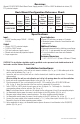
Rack Mount Configuration Reference Chart:
Altronix
Model Number
Output
Voltage
Total
Output
Current
(Power)
Number
of
Ouputs
PTC
Protected
Auto-
Resettable
Outputs
Output
Current
(max per
output)
220VAC
50/60Hz
Input
Current Agency Listing
R1224DC16CBV
12VDC 18A
16
P
2A
1.8A
CE European
Conformity
24VDC 18A
3.1A
Specifications:
Input:
• 220VAC (working range 198VAC - 256VAC),
50/60Hz.
Output:
• Sixteen (16) PTC protected outputs.
• 12VDC or 24VDC output.
• 18A total continuous supply current.
• Filtered and electronically regulated outputs.
• Surge suppression.
Visual Indicators:
• Power LED indicators per group of 4 outputs.
• Illuminated power disconnect circuit breaker with
manual reset.
Additional Features:
• Removable terminal blocks w/locking screw flange.
• IEC 320 - 3-wire grounded line cord (detachable).
• Ease of installation saves time and eliminates
costly labor.
Enclosure Dimensions:
3.26” x 19.125” x 8.5” (83mm x 486mm x 216mm).
CAUTION: This installation should be made by qualified service personnel and should conform to all
local codes and the National Electrical Code.
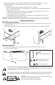
Installation Instructions:
1. Attach mounting brackets to the unit for rack mount installation (Fig. 1a, pg. 3). Affix rubber pads to the
unit for shelf installation (Fig. 2, pg. 3).
2. Secure the unit in a rack or place unit on a shelf as desired (unit should be spaced at least 3” from any
video monitors).
When installing the unit in a rack allow for one half of a U spacing above the unit for ventilation.
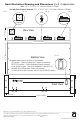
3. Insert and secure removable terminal blocks to the unit (Fig. 3c, pg. 4).
4. Plug the grounded AC line cord (included) into the IEC 320 connector of the R1224DC16CBV unit
(Fig. 3a, pg. 4). Insert the plug end of the line cord into a grounded AC receptacle.
5. Select 12VDC or 24VDC power for each group of four (4) outputs 1a - 1d through 4a - 4d with the
corresponding voltage selector switches (Fig. 3b, pg. 4).
Note: Each voltage selector switch sets the voltage for the entie group of four (4) corresponding outputs.
6. Set illuminated master power disconnect circuit breaker to the (ON) position (Fig. 3d, pg. 4).
7. Measure output voltage before connecting devices. This helps avoiding potential damage.
8. Set illuminated master power disconnect circuit breaker to the (OFF) position (Fig. 3d, pg. 4).
9. Connect the power output of the terminals marked [+ 1A –] to the power inputs of device (Fig. 3c, pg. 4).
Repeat this step for the other remaining power outputs.
10. Upon completion of wiring, set illuminated master power disconnect circuit breaker to the ON (RESET)
position (Fig. 3d, pg. 4).