
Installation Instructions


- 2 - SMP3CTX series
2. Slide [Power ON/OFF] switch t o OFF position.
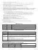
3. Set SW1 on the power supply board to the desired DC output voltage (Fig. 1c, pg. 3) (Power Supply Voltage
Output Specification Chart).
4. Connect AC power to the terminals marked [L & N], connect ground to the green flying lead (Fig. 1, pg. 3).
Use 18 AWG or larger for all power connections (Battery, DC output).
Use 22 AWG to 18 AWG for power-limited circuits (AC Fail/Low Battery reporting).
5. Slide [Power ON/OFF] switch to ON position.
6. Measure output voltage before connecting devices. This helps avoiding potential damage.
CAUTION: Do not touch exposed metal parts. Shut branch circuit power before installing or servicing equipment.
There are no user serviceable parts inside. Refer installation and servicing to qualified service personnel.
7. Slide [Power ON/OFF] switch t o OFF position.
8. Connect devices to be powered:
a. For Power Supply Board connect to the terminals marked [– DC +].
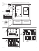
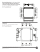
b. For Power Distribution Module(s) connect devices to be powered to the terminal pairs 1 to 4 marked
[1P & 1N] through [4P & 4N] (Fig. 2, pg. 3), 1 to 8 marked [1P & 1N] through [8P & 8N] (Fig. 3, pg. 3),
or 1 to 16 marked [1P & 1N] through [16P & 16N] (Fig. 4, pg. 3), carefully observing correct polarity.
Note: Power switch is used to disconnect the L (HOT) terminal from the rest of the board (Fig. 1a, pg. 3).
When servicing the unit, AC mains should be removed.
9. When using stand-by batteries, they must be lead acid or gel type.
Connect battery to the terminals marked [– BAT +] (battery leads included).
12VDC operation: Use one (1) 12VDC battery.
24VDC operation: Use two (2) 12VDC batteries connected in series.
Note: When batteries are not used, a loss of AC will result in the loss of output voltage.
For supervised models only:
10. Connect appropriate signaling notification devices to AC Fail and Low Bat supervisory relay outputs
marked [NC, C, NO] (Fig. 1b, pg. 3).
11. Slide [Power ON/OFF] switch to ON position.
LED Diagnostics:
Red (DC) Green (AC) Power Supply Status
ON ON Normal operating condition.
ON OFF Loss of AC. Stand-by battery supplying power.
OFF ON No DC output.
OFF OFF Loss of AC. Discharged or no stand-by battery. No DC output.
Terminal Identification:
Power Supply Board:
Terminal Legend Function/Description
L, G, N Connect 115VAC/230VAC to these terminals: L to Hot, N to Neutral.
– DC + 12VDC / 24VDC @ 2.5A continuous output.
*AC FAIL
NC, C, NO
Used to notify loss of AC power, e.g. connect to audible device or alarm panel. Relay normally
energized when AC power is present. Contact rating 1A @ 120VAC / 28VDC.
*Low Battery
NC, C, NO
Used to indicate low battery condition, e.g. connect to alarm panel. Relay normally
energized when DC power is present. Contact rating 1A @ 120VAC / 28VDC.
Low battery threshold:
12VDC output threshold set @ approximately 10.5VDC,
24VDC output threshold set @ approximately 21VDC.
– BAT + Stand-by battery connections. Maximum charge rate 0.5A.
*Note: Supervised models only
PD4/PD4CB/PD8/PD8CB/PD16W/PD16WCB - Power Distribution Module:
Terminal Legend
Function/ Description
PD4/PD4CB PD8/PD8CB PD16W/PD16WCB
1P to 4P 1P to 8P 1P to16P Positive DC power outputs.
1N to 4N 1N to 8N 1N to 16N Negative DC power outputs.