
Installation Instructions


SMP3CTX series - 3 -
Fig. 2 Fig. 4
Fig. 3
INPUT
LED
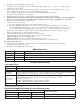
1P, 2P, 3P, 4P = FUSED OUTPUTS
1N, 2N, 3N, 4N = COMMON OUTPUTS
F1 F2 F3 F4
COMMON POWER OUTPUTS
1P
1N
2P
2N
3P
3N
4P
4N
DC Output to devices
From Power Supply
Board
(Factory Installed)
Used on
PTC Models
N
COMMON POWER OUTPUTS
P
FUSED POWER OUTPUTS
1 2 3 4 5 6 7 8
D1
INPUT
R1
LED
DC Output to devices
From Power Supply
Board
(Factory Installed)
ON OFF
SW1
Used on
PTC Models
Power Distribution Module(s):
common
outputs
protected
outputs
P
N
NPS
XFMR Input
12345678
9 10 11 12 13 14 15 16
P
N
3.5A 250V
For continuous protection against risk of fire
replace fuses with same type and rating.
Used on
PTC Models
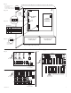
Power Supply
Board
LGN
ON OFF
AC DC
5A 250V
LOW BAT
NC C NO NC C NO
AC FAIL
--- BAT + --- DC +
Power
Distribution
Module(s)
CAUTION: De-energize unit prior to servicing. Do not expose to rain or moisture.
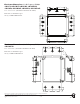
Green
Lead
Wire
Strap
(from
Enclosure
to Door)
115/230VAC
power
mains
INPUT
LOW BAT
NC C NO NC C NO
AC FAIL
Optional Rechargeable
Stand-by Battery
Optional Rechargeable
Stand-by Battery
CAUTION: Optional rechargeable stand-by batteries must match
the power supply output voltage setting.
Switch disables power mains
line voltage input.
If stand-by battery (batteries) are
connected, the DC output remains on.
ON OFF
Battery and AC
Supervision
Circuit
SW1
24VDC output - OFF
12VDC output - ON
LED Diagnostics
Red Green Power Supply Status
(DC) (AC)
ON ON Normal operating condition.
ON OFF Loss of AC. Stand-by battery
(batteries) supplying power.
OFF ON No DC output.
OFF OFF Loss of AC. Discharged or no stand-by
battery (batteries). No DC output.
ON
1
Switch On - 12V
Switch Off - 24V
OFF --- 2V
ON --- 2V
ON
Fig. 1
Fig. 1a
Fig. 1b
Fig. 1c