
Installation Guide

- 2 - Trove2SH2/TSH2 - Altronix/Software House
Altronix
Power Supply
Altronix
Power Supply or
Sub-Assembly
Metal Standoff Placement
Metal Standoff Placement
USB PORT
USB PORT
iStar
Ultra GCM
iStar Ultra ACM
iStar Ultra ACM
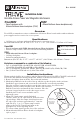
TSH2: Configuration of Altronix Power Supply
and/or Sub-Assembly Boards and Software House Boards
1. Fasten standoffs (provided) to pems that match the hole pattern for Altronix Power Supply/Chargers
or Altronix Sub-Assembly boards (Fig. 2, pg. 2).
Fasten metal standoffs in the correct locations to provide proper grounding, see below (Fig. 2, pg. 2).
2. Mount boards to standoffs utilizing 5/16” pan head screws (provided) (Fig. 2, pg. 2).
3. Align the Software House boards on the backplane to match the boards’ mounting holes
with pems provided.
4. Fasten standoffs (provided) to pems that match the hole pattern for Software House
iStar Ultra GCM and iStar Ultra ACM boards.
5. Mount Software House boards to standoffs utilizing 5/16” pan head screws (provided) (Fig. 2, pg. 2).
Note: Software House iStar Ultra ACM boards have one (1) USB port each.
Please orient boards in the appropriate position according to the Fig. 2 below.
6. Fasten backplane to Trove2 enclosure utilizing lock nuts (provided).
Fig. 2