D50 and D60 Harvest Header FD70 FlexDraper Combine Header OPERATOR’S MANUAL Part #169006 Rev.
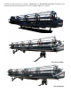
This Manual contains instructions for “SAFETY”, “OPERATION”, and “MAINTENANCE/SERVICE” information for your new MacDon Models D50 and D60 Harvest Header® and FD70 FlexDraper® for combines.
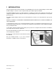
1 INTRODUCTION This instructional manual contains information on the D50/D60 Harvest Headers, FD70 FlexDraper, and the CA20 Combine Adapter. It must be used in conjunction with your Combine Operator's Manual. The FD70 FlexDraper header is specially designed as a “straight cut” header, and is equipped to work well in all straight cut conditions, whether cutting on or above the ground, utilizing a three piece flexible frame to closely follow ground contours.
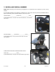
2 MODEL AND SERIAL NUMBER NOTE: Right hand (RH) and Left-hand (LH) designations are determined from the Operator’s position, facing forward. Record the Model Number, Serial Number, and Model Year of the Header, Slow Speed Transport/Stabilizer Wheel Option (if installed), and the Combine Adapter on the lines below: HEADER MODEL______________SERIAL NO._________________YEAR_____ Serial Number Plate is located on the left hand endsheet, near the knife drive motor. ADAPTER MODEL________SERIAL NO.
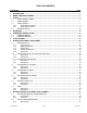
TABLE OF CONTENTS Section/Title 1 2 3 4 5 6 7 8 Page INTRODUCTION ............................................................................................................................................. 1 MODEL AND SERIAL NUMBER .................................................................................................................... 2 SAFETY ...................................................................................................................................................
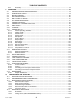
TABLE OF CONTENTS 8.2.2 Assembly ..................................................................................................................................... 75 9 OPERATION .................................................................................................................................................. 79 9.1 OWNER/OPERATOR RESPONSIBILITIES ........................................................................................ 79 9.2 OPERATIONAL SAFETY .............................
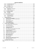
TABLE OF CONTENTS 10.5 LUBRICATION .................................................................................................................................. 139 10.5.1 Greasing Procedure .................................................................................................................. 139 10.5.2 Lubrication Points...................................................................................................................... 139 10.5.3 Oiling Requirements.......................
TABLE OF CONTENTS 10.14.10 Reel Drive Motor: D60, FD70 .................................................................................................... 203 10.14.11 Reel Drive Motor: D50 ............................................................................................................... 204 10.14.12 Reel Speed Sensor ................................................................................................................... 205 10.14.13 Reel Tines ......................................
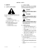
SECTION 3. SAFETY 3 SAFETY 3.2 3.1 Note the use of the signal words DANGER, WARNING, and CAUTION with safety messages. The appropriate signal word for each message has been selected using the following guidelines: SAFETY ALERT SYMBOL SIGNAL WORDS DANGER Indicates an imminently hazardous situation that, if not avoided, will result in death or serious injury. WARNING This safety alert symbol indicates important safety messages in this manual and on safety decals on the machine.
SECTION 3. SAFETY 3.3.2 Safety Decal Locations 3.3.2.
SECTION 3.
SECTION 3.
SECTION 3.
SECTION 3.
SECTION 3. SAFETY 3.3.2.
SECTION 3.
SECTION 3. SAFETY 3.3.2.
SECTION 3.
SECTION 3.
SECTION 3.
SECTION 3.
SECTION 3. SAFETY 3.4 GENERAL SAFETY CAUTION The following are general farm safety precautions that should be part of your operating procedure for all types of machinery. Protect yourself. When assembling, operating and servicing machinery, wear all the protective clothing and personal safety devices that COULD be necessary for the job at hand. Don't take chances. You may need: a hard hat. protective shoes with slip resistant soles. protective glasses or goggles. heavy gloves.
SECTION 3. SAFETY Use only service and repair parts made or approved by the equipment manufacturer. Substituted parts may not meet strength, design, or safety requirements. Do not modify the machine. Unauthorized modifications may impair the function and/or safety and affect machine life. Stop engine, and remove key from ignition before leaving Operator's seat for any reason. A child or even a pet could engage an idling machine. Keep the area used for servicing machinery clean and dry.
SECTION 4. DEFINITIONS 4 DEFINITIONS The following terms/abbreviations may be used in this manual: TERM DEFINITION API American Petroleum Institute ASTM American Society Of Testing and Materials Center-link A hydraulic cylinder or turnbuckle type link between the header and the machine that tilts the header. DK Double Knife GSL Ground Speed Lever Header A machine that cuts and lays crop into a windrow, and is attached to a self-propelled windrower or combine.
SECTION 5. COMPONENT IDENTIFICATION 5 COMPONENT IDENTIFICATION 5.
SECTION 5. COMPONENT IDENTIFICATION 5.
SECTION 6. SPECIFICATIONS 6 SPECIFICATIONS HEADER MODEL D60 D50 / D60 HEADER SIZE 20 FT 25 FT D50 / D60 / FD70 30 FT D60 / FD70 D60 / FD70 35 FT 40 FT 45 FT 495.1 (12575) 555.1 (14099) 601.5 (15278) 631.5 (16040) OVERALL Width (Inches (mm)) Length (Inches (mm)) Transport (Reel Full Aft) With CA20 Adapter Field Transport (with Tow Pole) 96 (2438) 255.1 (6479) 315.1 (8003) 375.1 (9527) 435.1 (11051) D50, D60 Not Applicable 505.7 (12845) 547.5 (13907) FD70 Not Applicable 513.
SECTION 6. SPECIFICATIONS HEADER MODEL D60 D50 / D60 HEADER SIZE 20 FT 25 FT D50 / D60 / FD70 30 FT D60 / FD70 D60 / FD70 35 FT 40 FT 45 FT REEL Drive Hydraulic From Combine Hydraulic Oil Supply Speed 0 - 67 rpm Quantity of Tine Tubes 6/9 5/6/9 Effective Reel Diameter 5/6 5 65 in. (1650 mm) Finger Tip Radius Range 30.2 - 31.5 in. (766 - 800 mm) Plastic --- Standard Finger Type Heavy Duty Plastic Std. Optional D60 & 30 FT FD70 Finger Spacing Opt. D60 DK --- 6.0 in. (152.
SECTION 7. HEADER ATTACHMENT / DETACHMENT 7.1.1 7 HEADER ATTACHMENT / DETACHMENT The header/adapter is configured to each particular model of combine at the factory. These combines are: COMBINE Center-Link Kit Some combine models require shorter center-link components to ensure clearance to the combine cab. SECTION Case IH 7010, 8010, 7120, 8120, 5088, 6088, 7088 7.2 Case IH 2300, 2500 Series 7.3 John Deere 60, 70 Series 7.4 John Deere 50 Series 7.5 CAT Lexion 400, 500 (R Series) 7.
SECTION 7. HEADER ATTACHMENT / DETACHMENT 7.1.2 Flighting Extensions 7.1.3 Stripper Bars Flighting extension kits may have been supplied with your header to improve feeding in certain crops such as rice. Installation instructions are included with the kits. Stripper bar kits may have been supplied with your header to improve feeding in certain crops such as rice. Installation instructions are included with the kits. They are not recommended in cereal crops. They are not recommended in cereal crops.
SECTION 7. HEADER ATTACHMENT / DETACHMENT 7.1.4 CR Feeder Deflectors For New Holland CR 960, 9070, and 9080 combines, feeder kits have been installed on the adapter at the factory to improve feeding into the feeder house. A They may also have been installed as an option on older machines. If necessary, they can be removed. CA20 adapters for the CR Models listed have short feeder kits installed at the factory.
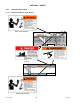
SECTION 7.2 CASE IH 7010, 8010, 7120, 8120, 88 SERIES 7.2 CASE IH 7010, 8010, 7120, 8120, 5088, 6088, 7088 D C 7.2.1 Attachment E IMPORTANT Some combine models require special center-link components to ensure clearance to the combine cab. F To avoid damage to your combine, lift feeder slowly and check clearance between cab and header center-link. c. Lift lever (C) on adapter at left side of feeder house, and push handle (D) on combine to engage locks (E) on both sides of the feeder house. d.
SECTION 7.2 CASE IH 7010, 8010, 7120, 8120, 88 SERIES L O M j. 3. Remove coupler (L) from combine, and clean mating surfaces. Rotate disc (O) on adapter driveline storage hook, and remove driveline from hook. M Q G J P k. K R 4. Position onto adapter receptacle (G), and push handle (K) to engage coupler pins into receptacle. 5. Push handle to “closed position” until lock button (J) snaps out. g. Remove cover on adapter electrical receptacle (N). See illustration on previous page. h.
SECTION 7.2 CASE IH 7010, 8010, 7120, 8120, 88 SERIES IMPORTANT 7.2.2 If stabilizer wheels are installed, set wheels to storage or “uppermost working position”. Otherwise header may tilt forward so that re-attachment will be difficult. Refer to Section 9.11.2 Cutting Height. Detachment a. Choose a level area. Position header slightly above ground. Stop engine, and remove key.
SECTION 7.2 CASE IH 7010, 8010, 7120, 8120, 88 SERIES E F F K G H G h. Push handle (G) to “closed position” until lock button (F) snaps out. Close cover (K). d. Remove electrical connector (E), and replace cover. M H E L N J e. Push in lock button (F), and pull handle (G) to release coupler (H). Position coupler (H) onto storage plate (J) on combine. Place electrical connector (E) in storage cup on plate (J) f. j. k. g. Form 169006 i.
SECTION 7.3 CASE IH 2300, 2500 SERIES 7.3 CASE IH 2300, 2500 SERIES A 7.3.1 Attachment a. Attach adapter to combine as follows: Sliding Pin System B 4. Lower handle (A) to engage pins (B) into adapter. 5. Proceed to step c. on next page. Latch System A WARNING To avoid bodily injury or death from unexpected start-up or fall of raised attachment, stop engine, remove key, and engage lift cylinder stop before proceeding with hook-up. B 1.
SECTION 7.3 CASE IH 2300, 2500 SERIES 5. Tighten jam-nuts (J) when force is correct. 6. Install pin (E) as shown to secure latch handle in “locked position”. b. Remove combine header lift cylinder locks, and lower header to ground. c. Connect combine hydraulics to adapter as follows: O 4. Remove plug from reel lift coupler (O) (black disc) on combine. K P 5. Remove red dust cap from reel lift hose (P) on adapter, and connect hose to combine coupler (O). L Q 1.
SECTION 7.3 CASE IH 2300, 2500 SERIES S g. Pull back collar on end of driveline, and push onto combine output shaft (X) until collar locks. Close guard (V). T Q R Y 7. Connect hose (Q) from combine to adapter coupler (S). 8. Connect hose (R) from the adapter to the combine coupler (T). h. If adapter is equipped with reel fore-aft/header tilt selector, connect harness (Y) to combine. U1 Z U A d.
SECTION 7.3 CASE IH 2300, 2500 SERIES IMPORTANT If stabilizer wheels are installed, set wheels to storage or “uppermost working position:. Otherwise header may tilt forward so that re-attachment will be difficult. Refer to Section 9.11.2 Cutting Height. 7.3.2 Detachment a. Choose a level area. Position header slightly above ground. Stop engine, and remove key.
SECTION 7.3 CASE IH 2300, 2500 SERIES O H K h. If adapter is equipped with reel fore-aft/header tilt selector, disconnect harness (H), and store on combine. i. Disconnect hydraulics as follows: 3. Connect hose (K) from the adapter to the adapter coupler (O). P J K P 1. Disconnect reel drive hoses (J) and (K) (white discs) from adapter and combine receptacles. M 4. J CAUTION 2. Connect hose (J) from combine to combine coupler (M).
SECTION 7.3 CASE IH 2300, 2500 SERIES j. T R Q Disengage adapter from combine with one of the following two methods depending on combine model. Latch System 1. Raise feeder house fully, and engage combine header lift cylinder locks. W V 5. Re-install plug on combine coupler (Q). X S 2. Remove pin (V), and lower latch handle (W) (one on each side of feeder house) to disengage latch (X). 3. Raise latch handle to “storage position”, and secure with pin (V). 4. Proceed to step k. below. R 6.
SECTION 7.4 JOHN DEERE 60, 70 SERIES 7.4 JOHN DEERE 60, 70 SERIES Contour Master, Level Land 7.4.1 Attachment B f. Check that bolts (E) on adapter brackets are tight. g. If pins (B) do not fully engage adapter brackets, loosen bolts (E), and adjust bracket as required. Re-tighten bolts. h. Remove blocks from under cutterbar. i. Start engine, and lower header. A C E D B a. Push handle (A) on combine coupler toward feeder house to retract pins (B) at bottom corners of feeder house. b.
SECTION 7.4 JOHN DEERE 60, 70 SERIES K Q G L P A 2. Locate coupler (G) onto receptacle, and pull handle (A) so that lugs on coupler are engaged into handle. 3. Pull handle to “full horizontal position” as shown. 4. Slide latch (K) to lock handle in position, and secure with lynch pin (L). n. If adapter is equipped with reel fore-aft/header tilt selector, connect harness (P) to combine. O R LOCK UNLOCK NOTE M l. Connector (P) may need to be retrieved from hydraulics compartment access hole (Q).
SECTION 7.4 JOHN DEERE 60, 70 SERIES IMPORTANT 7.4.2 Detachment If stabilizer wheels are installed, set wheels to storage or “uppermost working position”. Otherwise header may tilt forward so that re-attachment will be difficult. Refer to Section 9.11.2 Cutting Height. a. Choose a level area. Position header slightly above ground. Stop engine, and remove key.
SECTION 7.4 JOHN DEERE 60, 70 SERIES f. Disconnect hydraulic/electrical coupler (G) from combine as follows: J G H K 1. Remove lynch pin (H), and slide lock (J) to release handle (K). 2. Lift handle (K) to “full vertical position” to release coupler (G) from combine. M L 3. Lift handle (L) on adapter, position coupler in adapter at (M), and lower handle (L) to lock coupler. K O P N g. Push handle (K) toward feeder house to disengage feeder house pin (N) from adapter. h.
SECTION 7.5 JOHN DEERE 50 SERIES 7.5 JOHN DEERE 50 SERIES Contour Master, Level Land 7.5.1 Attachment A E d. Engage pins (A) in adapter. e. Check that bolts (E) on adapter brackets are tight. f. If pins (A) do not fully engage adapter brackets, loosen bolts (E), and adjust bracket as required. Re-tighten bolts. B REEL AFT ELECTRICAL A a. Retract pins (A) at bottom corners of feeder house. See Combine Operator’s manual. REEL LIFT g.
SECTION 7.5 JOHN DEERE 50 SERIES n. Close driveshield (H) on combine. H N M k. o. If adapter is equipped with reel fore-aft/header tilt selector, connect harness (M) to combine. Open shield (H) on combine. NOTE Connector (M) may need to be retrieved from hydraulics compartment access hole (N). O J P l. Rotate disc (J) on adapter driveline storage hook, and remove driveline from hook. LOCK UNLOCK p.
SECTION 7.5 JOHN DEERE 50 SERIES IMPORTANT If stabilizer wheels are installed, set wheels to storage or “uppermost working position”. Otherwise header may tilt forward so that re-attachment will be difficult. Refer to Section 9.11.2 Cutting Height. 7.5.2 Detachment a. Choose a level area. Position header slightly off the ground. Stop engine, and remove key. B DANGER To avoid bodily injury or death from fall of raised machine, always engage lift cylinder stops before going under header for any reason.
SECTION 7.5 JOHN DEERE 50 SERIES ELECTRICAL REEL AFT H REEL LIFT f. At left side of adapter, close valve on reel aft line. Disconnect both hydraulic lines and electrical cable. Attach caps and plugs, and store on combine. REEL FORE J REEL DRIVE i. j. Lower feeder house until saddle (H) disengages and clears adapter support (J). Slowly back combine away from adapter. g. At right side of adapter, disconnect the three hydraulic lines. Attach caps and plugs, and store hoses on combine. G h.
SECTION 7.6 CAT LEXION 400, 500 SERIES 7.6 CAUTION CAT LEXION 400, 500 SERIES Stop engine, and remove key from ignition before leaving Operator's seat for any reason. A child or even a pet could engage an idling machine. 7.6.1 Attachment B A E e. Remove locking pin (E) from adapter pin (B). B A a. Handle (A) on the CA20 adapter should be in “raised position”, and pins (B) at bottom corners of adapter retracted. b.
SECTION 7.6 CAT LEXION 400, 500 SERIES g. Connect hydraulic hoses as follows: Lexion 400 Attachment Lexion 500 Attachment G M F L H 1. Unscrew knob (L) on combine coupler (M) to release coupler from combine receptacle. 1. Unscrew knob (F) on combine coupler (G) to release coupler from combine receptacle (H). N J O N 2. Remove cover (J) from adapter receptacle. G J 2. Remove cover (N) from adapter receptacle, and place on combine receptacle (O). F M 3.
SECTION 7.6 CAT LEXION 400, 500 SERIES h. If adapter is equipped with reel fore-aft/header tilt selector, connect harness (U) to combine harness (V). (shown in previous column). Q R W 4. Disconnect hoses (Q) and (R) on combine at couplers. S i. Rotate disc (W) on adapter driveline storage hook, and remove driveline from hook. T X 5. Clean couplers (S) and (T) on adapter. 6. Connect hose (R) to coupler (S) on adapter. 7. Connect hose (Q) to coupler (T) on adapter. U j.
SECTION 7.6 CAT LEXION 400, 500 SERIES IMPORTANT If stabilizer wheels are installed, set wheels to storage or “uppermost working position”. Otherwise header may tilt forward so that re-attachment will be difficult. Refer to Section 9.11.2 Cutting Height. 7.6.2 Detachment a. Choose a level area. Position header slightly off the ground.
SECTION 7.6 CAT LEXION 400, 500 SERIES f. Disconnect hydraulics/electrical from adapter as follows: Lexion 500 Detachment Lexion 400 Detachment 1. Disconnect electrical harness from adapter. L N H F M G 1. Unscrew knob (F) on coupler (G) to release coupler from adapter. 2. Remove cover (H) from combine receptacle. G J K F 2. Disconnect hydraulic hoses from adapter connectors (L) and (M). Locate hoses (J) and (K) on combine as shown, and re-connect. 3.
SECTION 7.6 CAT LEXION 400, 500 SERIES W V O 5. Place cover (O) on adapter receptacle. W P Q V i. j. k. Lower feeder house to ground until feeder house posts (V) disengage adapter (W). Lower feeder. Slowly back combine away from adapter. 6. Locate coupler onto combine receptacle (P), and turn knob (Q) to secure coupler to receptacle. U T S g. Remove locking pin (S) from adapter pin (T). h. Raise handle (U) to disengage adapter pins (T) from feeder house.
SECTION 7.7 NEW HOLLAND CR, CX 7.7 NEW HOLLAND CR, CX A 7.7.1 Attachment B F B A a. Ensure handle (A) is positioned so that hooks (B) can engage adapter. D E G d. Lift lever (E) on adapter at left side of feeder house, and push handle (A) on combine so that hooks (B) engage pins (F) on both sides of the feeder house. e. Push down on lever (E) so that slot in lever engages handle to lock handle in place. f.
SECTION 7.7 NEW HOLLAND CR, CX g. Connect to receptacle on adapter as follows: N L O K J 2. Remove connector (N) from combine. 3. Align lugs on connector (N) with slots in adapter receptacle (O), and push connector onto receptacle. Turn collar on connector to lock it in place. M 1. Open cover (J). 2. Push in lock button (K), and pull handle (L) halfway up to “open position”. P H i. Rotate disc (P) on adapter driveline storage hook, and remove driveline from hook. 3.
SECTION 7.7 NEW HOLLAND CR, CX IMPORTANT If stabilizer wheels are installed, set wheels to storage or “uppermost working position”. Otherwise header may tilt forward so that re-attachment will be difficult. Refer to Section 9.11.2 Cutting Height. 7.7.2 Detachment a. Choose a level area. Position header slightly off the ground. Stop engine, and remove key. DANGER To avoid bodily injury or death from fall of raised machine, always engage lift cylinder stops before going under header for any reason.
SECTION 7.7 NEW HOLLAND CR, CX L J 3. Position coupler (E) onto storage plate (J) on combine. (shown on previous page) e. Remove electrical connector (K) from adapter, and connect to combine at (L). Replace cover on adapter receptacle. N O f. M Lift lever (M), and pull and lower handle (N) to disengage feeder house/adapter lock (O). Q P g. Lower feeder house until feeder house (P) disengages adapter support (Q). h. Slowly back combine away from adapter.
SECTION 7.8 AGCO 7.8 a. Retract lugs (A) at base of feeder-house with lock handle (B) (see picture opposite column). AGCO ALL EXCEPT GLEANER ‘R’ SERIES and ‘LL’ MODEL D Gleaner R Series, A Series, Challenger 660, 670, 680B, Massey 9690, 9790, 9895 7.8.1 Attachment IMPORTANT Some combine models require special center-link components to ensure clearance to the combine cab. GLEANER ‘R’ SERIES To avoid damage to your combine, lift feeder slowly, and check clearance between cab and header center-link.
SECTION 7.8 AGCO f. Connect adapter hydraulic quick coupler to combine receptacle as follows: F H G c. Raise feeder house to lift adapter, ensuring feeder house saddle (F) and alignment pins are properly engaged in adapter frame. d. Raise header slightly off the ground. 1. Pull handle (G) to release coupler (H) from adapter. J K CAUTION Stop engine, and remove key from ignition before leaving Operator's seat for any reason. A child or even a pet could engage an idling machine.
SECTION 7.8 AGCO Q M R LOCK N UNLOCK j. Disengage both adapter float locks by moving latch (Q) away from adapter, and moving lever (R) at each lock to “lowest position”. h. Pull back collar (M) on end of driveline, and push onto combine output shaft (N) until collar locks. O P i. Connect selector valve wire harness (O) to combine harness (P).
SECTION 7.8 AGCO IMPORTANT If stabilizer wheels are installed, set wheels to storage or “uppermost working position”. Otherwise header may tilt forward so that re-attachment will be difficult. Refer to Section 9.11.2 Cutting Height. 7.8.2 Detachment a. Choose a level area. Position header slightly off the ground. Stop engine, and remove key B DANGER To avoid bodily injury or death from fall of raised machine, always engage lift cylinder stops before going under header for any reason.
SECTION 7.8 AGCO e. Disconnect hydraulic/electrical coupler from combine as follows: ALL EXCEPT GLEANER ‘R’ SERIES K F GLEANER ‘R’ SERIES K J 1. Move handle (F) to “full open position” to release coupler from combine. H f. Retract lugs (J) at base of feeder-house with lock handle (K). L G 2. Lift handle (G) on adapter, position coupler (H) in adapter, and lower handle (G) to lock coupler. M g. Lower feeder house until saddle (L) disengages and clears adapter support (M). h.
SECTION 8.1 D50, D60 HEADER AND ADAPTER CAUTION 8 HEADER/ADAPTER DISASSEMBLY AND ASSEMBLY Wear heavy gloves when working around or handling sickles. A Using this procedure, the adapter remains attached to the combine, and is appropriate when: detaching the headers for use on a windrower, changing headers, or performing certain maintenance tasks. The procedure is the same for all makes and models of combines.
SECTION 8.1 D50, D60 HEADER AND ADAPTER h. Disconnect eye type hydraulic center-link as follows: H K G F e. Lower stand (F) by pulling spring loaded pin (G). Release pin when stand at desired height. f. Remove pin (H) from leg on both sides of adapter. g. Disconnect hook type hydraulic center-link as follows: i. 1. Operate center-link hydraulics until pin (K) is loose. 2. Remove pin (K), and lift center-link clear of bracket. 3. Replace pin (K), and secure with lynch pin.
SECTION 8.1 D50, D60 HEADER AND ADAPTER k. If quick disconnects are installed, disconnect as follows: o. If multi-coupler is installed, disconnect as follows: P N M O l. Q 1. Line up slot (M) in collar with pin (N) on connector. 2. Push collar toward pin, and pull connector to disengage. 3. Install plugs or caps on hose ends (if equipped). Disconnect electrical connector by turning collar counter clockwise, and pulling connector to disengage. m. Store and secure hoses on adapter. n.
SECTION 8.1 D50, D60 HEADER AND ADAPTER 8.1.2 Assembly The D50 and D60 Harvest Header can be attached to the adapter from either Field configuration or Transport configuration. F NOTE HOOK TYPE Stabilizer/Transport wheels can be used in combination with the stand to support header. A F EYE TYPE c. Prop up center-link (F) (hydraulic shown) with pin (or equivalent tool). a. Remove lynch pin, and remove pin (A) from each header leg. Temporarily store in safe place for re-installation. b.
SECTION 8.1 D50, D60 HEADER AND ADAPTER 3. Adjust length of link by operating header angle hydraulics to align with header bracket. h. Connect hook type hydraulic center-link as follows: H K J 1. Extend hook (H), and remove prop under link so that base of hook rests on pin (J). 2. Operate header angle hydraulics to retract hook until it engages pin and self-latches. j. M CAUTION Stop engine, and remove key from ignition before leaving Operator's seat for any reason.
SECTION 8.1 D50, D60 HEADER AND ADAPTER l. m. Secure header to adapter as follows: If multi-coupler is installed, connect as follows: O Q G N 1. Push in lock button (N), and pull handle (O) to “full open position”. 2. Clean couplers. O A R 1. Ensure adapter arm is properly located in header leg (G). Re-install pin (A) in each leg to lock header to adapter, and secure with lynch pin. 2. Return stand (Q) to “storage position”, and secure with pin (R). n. Lower header to ground. o.
SECTION 8.1 D50, D60 HEADER AND ADAPTER KNIFE DRIVE ELECTRICAL q. Attach adapter deck to header cutterbar as follows: CASE DRAIN (DOUBLE KNIFE) WARNING RETURN DRAPER DRIVE Keep hands clear of the area between guards and sickle at all times. CAUTION r. s. Wear heavy gloves when working around or handling sickles. Connect knife and draper drive hydraulics as shown above, using colored plastic ties as a guide. If quick disconnects are installed, proceed as follows: 1.
SECTION 8.1 D50, D60 HEADER AND ADAPTER u. Raise and lower header and reel a few times to allow trapped air to pass back to the reservoir. NOTE It is not necessary to bleed the system by loosening fittings. v. Check float and if the header is level. If adjustments are required, refer to Section 9.11.3 Header Float, and Section 9.14 HEADER LEVELLING.
SECTION 8.2 FD70 FLEXDRAPER AND ADAPTER f. 8.2 FD70 FLEXDRAPER/ADAPTER Remove the wing float linkage springs from the adapter as follows: C 8.2.1 Disassembly a. Choose a level area, and place 6 inch (150 mm) blocks under hinge area of cutterbar. REEL CUTTERBAR B FROWN 6 INCH BLOCKS LEVEL GROUND b. Lower header onto blocks so that header goes into a ‘full frown’. c. Fully retract tilt cylinder, and raise reel fully. d. Stop engine, remove key, and engage reel props. Refer to Section 9.
SECTION 8.2 FD70 FLEXDRAPER AND ADAPTER D J K E i. Lower stand (J) by removing pin (K). Re-install pin when stand at desired height. NOTE 45 FT header does not have a stand. Use blocks at this location. F D G DANGER 3. Rotate latch (D) with a 15/16 wrench on hex (E) to raise feed deck so that bolt (F) can be removed. Repeat for other side of feed draper deck. 4. Rotate latches to lower adapter deck. 5. Remove chain (G) from hook. Rotate latch back to original position, and re-install bolts (F).
SECTION 8.2 FD70 FLEXDRAPER AND ADAPTER m. Disconnect hook type hydraulic center-link as follows: ELECTRICAL KNIFE DRIVE M RETURN CASE DRAIN (DOUBLE KNIFE) 1. Lift release (M), and latch it in “up position”. 2. Extend center-link cylinder to disengage hook from header. Stop engine, and remove key. 3. Prop up center-link with a pin (or equivalent tool). 4. Go to step o. in next column. n. Disconnect eye type hydraulic center-link as follows: DRAPER DRIVE o.
SECTION 8.2 FD70 FLEXDRAPER AND ADAPTER s. Disconnect reel hydraulics as follows: T R Q w. Re-install bolts (T), washers, and spacers removed in step k. into adapter legs. S 1. Push in lock button (Q), and pull handle (R) to release coupler (S). 2. Push handle down until button (Q) snaps out. 3. Store hoses over adapter frame. t. Ensure header is on ground, or is supported by wheels in Transport mode. u. Start engine, and slowly back combine away from header. v. Stop engine, and remove key.
SECTION 8.2 FD70 FLEXDRAPER AND ADAPTER 8.2.2 Assembly The FD70 FlexDraper can be attached to the adapter from either Field configuration or Transport configuration. C B NOTE Stabilizer/Transport wheels can to be used in combination with the stand to support header. Refer to Section 9.11.2 Cutting Height. b. Start engine, and lower combine feeder house so that adapter arms (B) are aligned with header balance channel (C). Stop engine, and remove key. D A HOOK TYPE c.
SECTION 8.2 FD70 FLEXDRAPER AND ADAPTER g. Connect hook type hydraulic center-link as follows: G E F 4. Insert pin (G), and secure with lynch pin. 1. Extend hook (E), and remove prop under link so that base of hook rests on pin (F). 2. Operate header angle hydraulics to retract hook until it engages pin and self-latches. CAUTION Stop engine, and remove key from ignition before leaving Operator's seat for any reason. A child or even a pet could engage an idling machine. 3.
SECTION 8.2 FD70 FLEXDRAPER AND ADAPTER IMPORTANT Do not install bolt 1½ inches (38 mm). longer than J N H K O k. 3. Position coupler (K) from adapter onto receptacle, and push handle (J) to engage pins on coupler. 4. Push handle to “closed position” until lock button (H) snaps out. Secure header to adapter as follows: CAUTION Always connect center-link before fully raising header. 1. Raise adapter slowly, making sure adapter legs engage in header legs.
SECTION 8.2 FD70 FLEXDRAPER AND ADAPTER s. If quick disconnects are installed, connect as follows: 1. Remove covers (if installed) from receptacles and hose ends. 2. Check connectors and clean if required. Q T p. Rotate latch (Q) with a 15/16 wrench (or equivalent) on hex (T) to raise feed deck so that bolt (P) can be re-installed. Repeat for other side of feed deck. q. Attach the wing float linkage to the adapter as follows: 3.
SECTION 9. OPERATION 9.2 9 OPERATION 9.1 OPERATIONAL SAFETY Follow these safety precautions: OWNER/OPERATOR RESPONSIBILITIES CAUTION Follow all safety and operational instructions given in your Operator's Manuals. If you do not have a combine manual, get one from your MacDon Dealer and read it thoroughly. Never attempt to start the engine or operate the machine except from the combine seat. Check the operation of all controls in a safe clear area before starting work.
SECTION 9. OPERATION Never attempt to get on or off a moving machine. Do not leave Operator’s station while the engine is running. Stop engine, and remove key before adjusting or removing plugged material from the machine. A child or even a pet could engage the drive. 9.3 Check for excessive vibration and unusual noises. If there is any indication of trouble, shut down and inspect the machine. Follow proper shutdown procedure. Refer to Section 9.6 SHUTDOWN PROCEDURE.
SECTION 9. OPERATION 9.5 DAILY START-UP CHECK 9.6 SHUTDOWN PROCEDURE Do the following each day before start-up: CAUTION CAUTION Clear the area of other persons, pets etc. Keep children away from machinery. Walk around the machine to be sure no one is under, on, or close to it. Wear close fitting clothing and protective shoes with slip resistant soles. Remove foreign objects from the machine and surrounding area.
SECTION 9. OPERATION 9.7 9.9 HEADER CONTROLS CAUTION WARNING Be sure all bystanders are clear of machine before starting engine or engaging any header drives. See your Combine Operator's Manual for identification of in-cab controls for: 9.
SECTION 9. OPERATION D50 Header a. Raise reel to maximum height. B A C FD70 FLEXDRAPER b. Move props (A) to engaged position. c. Lower reel until props contact end frames. NOTE: Keep pivot bolt (B) properly tightened so prop remains in stored position when not in use, yet can be engaged with hand force. C d. To disengage reel props, raise reel, push arm props (A) back against reel arm. D60 HARVEST HEADER D c.
SECTION 9. OPERATION 9.10 STORAGE Do the following at the end of each operating season: a. Clean the header thoroughly. CAUTION Never use gasoline, naphtha or any volatile material for cleaning purposes. These materials may be toxic and/or flammable. CAUTION Cover cutterbar and sickle guards to prevent injury from accidental contact. b. Store the machine in a dry, protected place if possible. If stored outside, always cover with a waterproof canvas or other protective material. c.
SECTION 9. OPERATION 9.11 HEADER SET-UP The following Table is included as a guideline for setting the pickup reel and the header. Settings other than those suggested can be made to suit various crops and conditions not covered in the table. To use the Table, proceed as follows: 1. 2. 3. 4. 5. Determine crop type to be cut. Determine desired stubble length. Determine condition of the crop. Locate the most suitable set-up for the reel. Refer to Chart that starts on the next page for reel settings.
SECTION 9.
SECTION 9.
SECTION 9.
SECTION 9. OPERATION 9.11.1 Header Operating Variables Satisfactory function of the header in all situations requires making proper adjustments to suit various crops and conditions. Correct operation reduces crop loss and allows cutting of more acres. As well, proper adjustments and timely maintenance will increase the length of service you receive from the machine. The variables listed below and detailed on the following pages will affect the performance of the machine.
SECTION 9. OPERATION 4. Lower header to desired cutting height using combine controls, and check spring length as shown. Re-adjust wheels as required to achieve range. 2. Adjust left wheels as follows: H Release G IMPORTANT Continuous operation with excessive spring compression (i.e. spring length 12.6 in +/-1.0 shorter than 295 (320 mm +/-25) mm) can result in damage to suspension system. Lock i. d.
SECTION 9. OPERATION 9.11.2.2 4. Re-install pin (C), engage in frame, and secure with lynch pin (A). Cutting On The Ground Cutting on the ground is controlled with a combination of skid shoes, header angle, and float adjustment, and not with the header lift cylinders. Inner Skid Shoes Having the header "ride" on the skid shoes allows the float linkage to float the header over obstacles and follow ground contours, rather than supporting the header with the cylinders.
SECTION 9. OPERATION 9.11.3 Header Float D50, D60, and FD70 combine headers perform best with minimum extra weight on the header, under normal conditions. Check the float as follows: 9.11.3.1 Main Float Locks The function of the header main float locks are to lock and unlock the header float system. There are two locks - one on each side of the adapter. a. Disengage main float locks by moving latch (A) away from adapter, and moving lever (B) at each lock to “lowest position”.
SECTION 9. OPERATION D c. Set center-link to mid-range (B to C on float/angle indicator if installed). Adjust cutterbar to 6 - 10 inches (150 - 250 mm) above the ground. d. If header is equipped with stabilizer wheels or slow speed transport wheels, raise them off the ground so they are supported by the header. E RIGHT SIDE - BELL CRANK NOT SHOWN f. Place torque wrench (D) onto float setting indicator (E). Note position of wrench for checking RH or LH side. G D e.
SECTION 9. OPERATION 9.11.3.3 A Setting Feeder House Height and Header Angle B Y LEFT SIDE FLOAT X RIGHT SIDE FLOAT h. To increase float (lighten the header), tighten bolts (A) and (B) at both sides of adapter. i. To decrease float (increase header weight), loosen the bolts (A) and (B). IMPORTANT Turn each bolt pair equal amounts. After adjustment has been made, refer to Section 9.11.3.2 Checking and Adjusting Float. a.
SECTION 9. OPERATION 9.11.3.4 Adjusting Header Float: On Ground 9.11.3.5 This section shows how to adjust header float for proper flex action while on the ground. Wing Float Lock: FD70 The FD70 FlexDraper is designed to operate with the cutterbar on the ground. The three (3) sections move independently to follow the ground contours. In this mode, the wing float lock is unlocked.
SECTION 9. OPERATION 9.11.3.6 The following table summarizes the adjustment range: Wing Float Linkage Adjustments The wing float has been adjusted at the factory but the following adjustments may be necessary for optimum operation of the FD70 FlexDraper: Wing Balance Cutterbar Straightness In Lock Mode Wing Flex Range Refer to Section 10.15 HEADER WING FLOAT for details on performing these adjustments. HEADER WIDTH DRAPER ANGLE GUARD ANGLE 25 FT 13.0° - 18.4° 7.0° - 12.
SECTION 9. OPERATION 9.11.5 9.11.5.1 Reel Speed Reel speed affects feeding of crop into the sickle and onto the drapers, as well as the smoothness and evenness of the delivered crop. Operating the reel too fast or too slow relative to ground speed will cause bunching. At the proper speed, the reel discs should appear to be being driven by the ground.
SECTION 9. OPERATION 9.11.6 Ground Speed Higher ground speeds require heavier float settings to prevent excessive bouncing that would result in increased cutting component damage. Ground speed should be such that the sickle can cut crop smoothly and cleanly, while giving the desired delivery of material to the opening. Excessive ground speed results in "ragged" cutting. In most cases, as ground speed is increased, draper and reel speed should be increased to handle the extra material.
SECTION 9. OPERATION 9.11.7 Draper Speed A C B a. The speed of the header/side drapers (A) is adjusted at the flow control (B) on the combine adapter. b. Turn knob (B) “two turns from closed”, and then adjust draper speed to achieve good feeding of crop onto adapter draper. Excessive draper speed will reduce draper life. NOTE Three turns open produces full draper speed. NOTE If sufficient draper speed cannot be achieved, a possible cause is low relief pressure.
SECTION 9. OPERATION 9.11.8 WARNING Knife Speed The header knife drive is driven by the adapter mounted hydraulic pump. The knife drive speed is factory-set for a feeder house speed of 575 rpm for CNH and John Deere adapters, and 780 rpm for AGCO and Lexion adapters. Ensure bystanders are clear before starting. c. Start combine engine, engage the header drive, and run the combine at operating rpm. IMPORTANT For variable speed feeder houses, this will be the minimum speed setting.
SECTION 9. OPERATION IMPORTANT 9.11.10 Reel Fore-Aft Position Reel position has been found to be a critical factor in achieving good results in adverse conditions. The reel position is factory-set for average straight standing crop, and can be adjusted forward and backward for different crop conditions. Operating with the reel too far forward can cause the fingers to contact the ground before the Cutterbar.
SECTION 9. OPERATION 9.11.10.2 Hydraulic Adjustment: Fore-Aft a. Select the fore-aft adjust mode on the selector switch in the cab (if applicable). b. Operate the hydraulics to move the reel to the desired position, again using the gauge as a reference. c. Check reel clearance to cutterbar after making changes to cam setting. Refer to Section 10.14.1 (D50, D60) or 10.14.2 (FD70) Reel Clearance to Cutterbar for measurements and adjustment procedures. 9.11.10.
SECTION 9. OPERATION c. Re-position right arm cylinder (Double Reel) as follows: J NOTE Loosen a hose fitting to allow movement of cylinder. Be sure to re-tighten fitting after cylinder installation. 4. Re-install plates (J) and (L) with bolts (H) and (K) respectively. d. Re-position right arm cylinder (Single Reel) as follows: H N RIGHT ARM - DOUBLE REEL 1. Remove bolts (H) that secure plate (J), and remove plate. M O Q P L RIGHT ARM - SINGLE REEL 1.
SECTION 9. OPERATION e. Re-position left arm cylinder (Double and Single Reel) as follows: Q C B S R U D A LEFT ARM - SINGLE and DOUBLE REEL 5. Lift aft end of the cylinder out of the support assembly, and move cylinder so that cylinder center port fitting (U) engages the support assembly. NOTE Loosen a hose fitting to allow movement of cylinder. Be sure to re-tighten fitting after cylinder installation. N M O P 1. Loosen fitting (A) to allow it to rotate when cylinder is re-positioned. 2.
SECTION 9. OPERATION Cam Positions 3 and 4: Mainly used to leave long stubble. Allows the reel to reach forward and lift the crop across the knife and onto the drapers. The further forward the reel, the higher the cam setting should be. Cam Position 4 would be used with the reel being fully forward to leave maximum amount of stubble in lodged crops. This setting gives a finger tip speed approximately 30% faster than the reel speed.
SECTION 9. OPERATION 9.11.11.3 D50 Cam Adjustment WARNING Stop combine engine, and remove key before making adjustments to machine. A child or even a pet could engage the drive. D60, FD70 D A G D50 C a. Loosen bolt (D) on clamp securing cam disc to reel arm. B E D60 AND FD70 a. Using a ¾ in. wrench, turn the cam latch pin (A) counter clockwise to release the cam disc. IMPORTANT F Secure cam position before operating machine. b.
SECTION 9. OPERATION 9.11.12.2 9.11.12 Crop Dividers and Rods 9.11.12.1 The crop dividers are removable to suit installation of vertical knives, and to decrease transport width. Divider Rods Divider rods are removable. The removable divider rods are suitable when crop is down, while the crop divider without rods is better in standing crops. See chart below for recommended rod use for various crops.
SECTION 9. OPERATION D50 a. Raise header, and engage lift cylinder lockouts. Refer to combine operating manual. b. Open header endshield. Refer to Section 10.4 ENDSHIELDS AND COVERS. D B E A c. Position crop divider as shown by locating lugs (D) in holes in endsheet. F c. Remove bolt (A), lock-washer, flat washer, and lower divider (B). d. Lift divider off endsheet. e. Close header endshield. 9.11.12.4 G Installation D60, FD70 a. Open header endshield. d.
SECTION 9. OPERATION D50 9.11.12.5 Rice Dividers a. Open endshield. b. Remove from storage. B c. Position crop divider as shown by locating lugs (B) in holes in endsheet. Optional special rice dividers can be installed and used when required. See Section 12.15 RICE DIVIDER KIT. The installation and removal procedures are the same as for the standard crop dividers. A d. Lift forward end of divider, and install bolt (A), lock-washer, and flat washer. Tighten bolt. C e.
SECTION 9. OPERATION 9.12 DRAPER DEFLECTORS D60 single knife headers are equipped with rubber deflectors that are attached to the inboard side of the endsheets to prevent material from falling through the gap between endsheet and draper. In some cases, material hesitates on deflectors and will not flow onto draper. Replace existing deflector with a narrower one, or rework existing deflector. 9.12.1 Deflector Replacement a. Raise reel fully, and lower header. b. Shut down combine. Remove key.
SECTION 9. OPERATION 9.13 KNIFE HEAD SHIELD The shield attaches to the endsheet, and reduces the knife head opening to prevent cut crop from accumulating in knife head cut-out creating plugging. A It is recommended that the shield(s) be installed when harvesting severely lodged crop or any crop condition where plugging occurs at knife head cut-out.
SECTION 9. OPERATION 9.14 HEADER LEVELLING The adapter is factory-set to provide the proper level for the header, and should not normally require adjustment. 1. Turn low-side nut clockwise to raise header. 2. Turn high-side nut counter clockwise to lower header. If the header is not level, perform the following checks prior to adjusting the leveling linkages. IMPORTANT The adapter float springs are not used to level the header. Check combine tire pressures.
SECTION 9. OPERATION 9.15 UNPLUGGING CUTTERBAR a. Stop forward movement of machine, and disengage header drives. b. With header on ground, back up several feet, and engage header drive clutch. CAUTION Lowering rotating reel on a plugged cutterbar will damage the reel components. c. If plug does not clear, disengage header drive clutch, and raise header fully. WARNING Stop engine, and remove key before removing plugged material from header. A child or even a pet could engage the drive. d.
SECTION 9. OPERATION a. Lower header to ground, shut down combine, and remove key. 9.17 UPPER CROSS AUGER A C B DOUBLE REEL HEADERS The cross auger helps deliver very bulky crops across the header onto the windrow or into the combine. Removable beater bars assist in delivering material through the header opening, but if wrapping occurs, the beater bars can be removed as follows: C B WARNING Stop engine, and remove key before removing plugged material from header.
SECTION 9. OPERATION 9.18.2 9.18 TRANSPORTING HEADER WARNING Do not drive combine with header attached on a road or highway at night, or in conditions which reduce visibility, such as fog or rain. The width of the header may not be apparent under these conditions. Towing The headers can be towed behind the combine or with the Slow Speed Transport/Stabilizer Wheel option, or on an approved header transporter. Refer to your Combine Operator’s Manual, or see your MacDon Dealer. 9.18.2.
SECTION 9. OPERATION 9.18.2.2 Towing The Header 9.18.3 CAUTION THIS IS INTENDED TRANSPORT. AS SLOW SPEED Converting from Transport to Field Position a. Block the tires to prevent header rolling, and unhook from towing vehicle. b. Remove tow-bar as follows: CAUTION A To avoid bodily injury and or machine damage caused by loss of control: Do not exceed 25 mph (40 km/h). Reduce transport speed to less than 5 mph (8 km/h) for corners and slippery or rough conditions.
SECTION 9. OPERATION G 2. For clevis or pintle end of tow-bar, secure in support (L) on endsheet with hitch pin (M). Secure with lynch pin. 3. Install rubber strap (N) on cradle. 4. Similarly locate other section of tow-bar in cradle at other end of header. 5. Secure tube end in support (O) with clevis pin (P). Secure with hairpin. 6. Install rubber strap (N) on cradle. F H d. Attach header to combine. Refer to Section 7 HEADER ATTACHMENT/DETACHMENT. IMPORTANT c. 4.
SECTION 9. OPERATION 9.18.3.1 Front Wheels To Field Position DANGER Release C To avoid bodily injury or death from unexpected start-up or fall of raised header, stop engine, remove key, and engage header lift cylinder stops before going under header for any reason. a. Raise header fully. b. Swivel wheel assembly so that wheels are aligned with lower frame. Lock TRANSPORT TO FIELD - FRONT WHEELS d. Pull handle (C) to release and lower the linkage. A D E B F A TRANSPORT TO FIELD - FRONT WHEELS e.
SECTION 9. OPERATION 9.18.3.2 Rear Wheels To Field Position F A K a. Pull pin (A) at left wheel, swivel wheel clockwise, and lock with pin (A). J C TRANSPORT TO FIELD - RH WHEEL Release E Lock G H TRANSPORT TO FIELD - LH WHEEL f. At right cutterbar wheel, pull pin (F) on brace (G), disengage brace from cutterbar, and lower the brace against axle (H). g. Remove pin (J), lower the support (K) onto axle, and re-insert pin into support. h. Swing axle clockwise to rear of header.
SECTION 9. OPERATION IMPORTANT Check that wheels are locked and that handle is in “locked position”. FIELD POSITION - LH SIDE FIELD POSITION - RH SIDE m. The conversion is complete when the wheels are as shown.
SECTION 9. OPERATION c. 9.18.4 Converting from Field to Transport Position Place suspension assembly in “full upward position” (E) in leg, and lower handle (F) to lock. Raise header fully, and proceed as follows: DANGER To avoid bodily injury or death from unexpected start-up or fall of raised header, stop engine, remove key, and engage header lift cylinder stops before going under header for any reason. 9.18.4.
SECTION 9. OPERATION 9.18.4.2 Right Side Wheels To Transport Position A Release C B LOCK FIELD TO TRANSPORT - LH WHEEL D h. Left wheel is now in transport position as shown above. FIELD TO TRANSPORT - RH SIDE a. At wheels at the right end of header, remove hairpin (A) from latch. b. Lift latch (B), disengage right axle, and lower to ground. CAUTION J Stand clear of wheels and release linkage carefully as wheels will drop once the mechanism is released. c.
SECTION 9. OPERATION Q O P M N L TRANSPORT POSITION - RH WHEEL k. Remove pin (L), raise support (M) to position shown, and re-insert pin (L). IMPORTANT Ensure pin (L) engages the tube on the axle. l. Swing brace (N) into position as shown, and insert brace into slot (O) behind cutterbar. Position brace so that pin (P) engages hole in bracket (Q). m. Right hand wheel is now in transport position.
SECTION 9. OPERATION 9.19 WINDROWING The D60 Harvest Header can be used for windrowing with a combine, but it is necessary to modify the CA20 Combine Adapter by removing auger and feed deck as per the following procedure. The auger and feed deck can be re-attached for combining by reversing the following procedure. 9.19.1 E Adapter Modification D a. Remove header from adapter. Refer to Section 8.1.1 Disassembly. b. Place blocks under the adapter legs on level ground.
SECTION 9. OPERATION j. Disconnect hoses (M) at feed draper motor, and re-connect ends with a 5/8 inch JIC male to male fitting (shown in previous column). NOTE Mark hoses so that they are re-installed in the matching ports when re-installing the feed deck. Install plugs on motor ports. J K O N h. Tighten straps until float limiter bars (J) are loose. Remove pins (K) at lower end of bars. NOTE Float limiter bars are stamped with letter F. k. Loosen two bolts (N) that secure deck retaining pins (O).
SECTION 9. OPERATION 9.19.1.2 9.19.1.3 Auger and Transition Pan Removal Re-Position Deck A E a. Remove four bolts (A) that attach auger right hand support to adapter frame. b. Move auger to the right to allow auger left hand support to slide off auger drive shaft tube. c. Remove auger, and set aside for re-installation. a. Loosen bolt (E) on deck that is to be moved. b. Slide deck to close off center opening. Re-tighten bolt (E). B F C d.
SECTION 9. OPERATION F G 3. After deck is moved, attach backsheet to support (G) with hardware provided. 4. Tighten bolts. RIGHT DECK MOTOR NOTE If right deck is moved, loosen clamp on plastic sleeve at right deck drive motor so that hoses can be reversed. Re-tighten clamp. 9.19.1.4 Header Attachment a. Re-attach adapter to combine. Refer to Section 7 HEADER ATTACHMENT/DETACHMENT. b. Re-attach header to adapter. Refer to Section 8 HEADER/ADAPTER DISASSEMBLY AND ASSEMBLY. c. Adjust header float.
SECTION 10. MAINTENANCE AND SERVICING 10 MAINTENANCE AND SERVICING 10.2 RECOMMENDED SAFETY PROCEDURES The following instructions are provided to assist Operator in the use of header. Detailed maintenance, service, and parts information are contained in the Technical Manual and the Parts Catalog that are available from your MacDon Dealer. 10.1 PREPARATION FOR SERVICING Park on level surface when possible. Block wheels securely if combine is parked on an incline.
SECTION 10. MAINTENANCE AND SERVICING 10.3 MAINTENANCE SPECIFICATIONS 10.3.1 10.3.1.2 Metric Bolts Recommended Torques Tighten all bolts to the torques specified in chart (unless otherwise noted throughout this manual). Check tightness of bolts periodically, using bolt torque chart as a guide. Replace hardware with the same strength bolt. Torque figures are valid for non-greased or non-oiled threads and heads (unless otherwise specified).
SECTION 10. MAINTENANCE AND SERVICING 10.3.1.3 Flare Type Hydraulic Fittings 10.3.1.4 NUT FLARE O-Ring Type Hydraulic Fittings FITTING LOCKNUT WASHER O-RING GROOVE BODY FLARESEAT SEAT a. Check flare and flare seat for defects that might cause leakage. b. Align tube with fitting before tightening. c. Lubricate connection, and hand-tighten swivel nut until snug. d. To prevent twisting the tube(s), use two wrenches.
SECTION 10. MAINTENANCE AND SERVICING a. Check components to ensure that the sealing surfaces and fitting threads are free of burrs, nicks, and scratches, or any foreign material. b. Apply lubricant (typically Petroleum Jelly) to O-ring and threads. If O-ring is not already installed, install O-ring. Align the tube or hose assembly. c. Ensure that flat face of the mating flange comes in full contact with O-ring. d. Thread tube or hose nut until hand-tight.
SECTION 10. MAINTENANCE AND SERVICING 10.3.2 Roller Chain Installation 10.3.3 Sealed Bearing Installation a. Clean shaft and coat with rust preventative. CAUTION Stop engine, and remove key from ignition before leaving Operator's seat for any reason. A child or even a pet could engage an idling machine. a. Locate ends of chain on sprocket. F H G K J B b. Install flangette (F), bearing (G), second flangette (H) and lock collar (J). A NOTE E The locking cam is only on one side of the bearing. c.
SECTION 10. MAINTENANCE AND SERVICING 10.3.4 Recommended Fluids and Lubricants Your machine can operate at top efficiency only if clean lubricants are used. Use clean containers to handle all lubricants. Store in an area protected from dust, moisture, and other contaminants. LUBRICANT Grease SPEC. SAE MultiPurpose Gear Lubricant SAE 85W-140 Hydraulic Oil SAE 15W-40 Form 169006 DESCRIPTION USE CAPACITIES High Temperature Extreme Pressure (EP2) Performance With 1% Max.
SECTION 10. MAINTENANCE AND SERVICING 10.3.5 Conversion Chart INCH-POUND UNITS QUANTITY SI UNITS (METRIC) FACTOR UNIT NAME ABBR. UNIT NAME ABBR. Area acres acres x 0.4047 = hectares ha Flow US gallons per minute gpm x 3.7854 = liters per minute L/min Force pounds force lbf x 4.4482 = Newtons N inch in. x 25.4 = millimeters mm foot ft x 0.305 = meters m Power horsepower hp x 0.7457 = kilowatts kW x 6.
SECTION 10. MAINTENANCE AND SERVICING 10.4 ENDSHIELDS AND COVERS 10.4.1 Endshields Single knife headers are fitted with a hinged endshield on the LH end of the header for easy access to the header drive. The RH end is not hinged, but is still removable. Double knife headers are fitted with hinged endshields on both ends of the header. d. Push in shield where shown (opposite latch), and shield will self-latch. 10.4.1.1 Hinged a.
SECTION 10. MAINTENANCE AND SERVICING f. To achieve a snug fit between the aft end of the shield and header frame, loosen bolts (G), and adjust the latch (H) to re-position the shield (shown in previous column). X J d. Adjust the endshield to achieve the gap ‘X’ between the front end of shield and header frame in accordance with the following chart. TEMPERATURE Degrees ˚F (˚C) GAP ‘X’ Inches (mm) 25 (-4) 1.1 (28) 45 (7) 1.0 (24) 65 (18) 0.79 (20) 85 (29) 0.64 (16) 105 (41) 0.
SECTION 10. MAINTENANCE AND SERVICING 10.4.1.2 Non-Hinged 10.4.1.2.1 Adjustments NOTE a. To remove the endshield, press against latch in opening at (A) on inboard side of endsheet. Plastic endshields are subject to expansion or contraction depending on large temperature variations. Latch pin can be adjusted to compensate for dimensional changes. A a. Remove endshield. b. Lift up on shield, pull out and back to remove shield. E B C D b. Loosen bolts (D). c.
SECTION 10. MAINTENANCE AND SERVICING 10.4.2 Linkage Cover (FD70 FLEXDRAPER ONLY) A B F a. To remove balance linkage covers (A), remove screw (B), and lift outboard end of cover. G e. To achieve a snug fit between aft end of shield and header frame, loosen bolts (F), and adjust latch (G) to re-position shield. f. Tighten bolts (F). b. Rotate upward until inboard end can be lifted off. C c. To install the cover, locate inboard end over linkage and behind indicator bar (C). d.
SECTION 10. MAINTENANCE AND SERVICING 10.5.1 10.5 LUBRICATION CAUTION To avoid personal injury, before servicing header or opening drive covers, follow procedures in Section 10.1 PREPARATION FOR SERVICING. Refer to Section 10.3.4 Recommended Fluids and Lubricants for recommended greases. Greasing Procedure a. Wipe grease fitting with a clean cloth before greasing, to avoid injecting dirt and grit. b. Inject grease through fitting with grease gun until grease overflows fitting, except where noted. c.
SECTION 10. MAINTENANCE AND SERVICING 10.5.2 LUBRICATION POINTS (Cont’d) NOTE: REEL BEARING LUBE INTERVALS - 500 HOURS OR ONCE PER SEASON - WHICHEVER OCCURS FIRST. REEL CENTER BEARING (1 PLC) DOUBLE REEL ONLY REEL DRIVE CHAIN (1 PLC) DOUBLE REEL SHOWN SINGLE REEL SIMILAR REEL SHAFT RH BEARING (1 PLC) REEL UNIVERSAL (1 PLC) U-JOINT HAS AN EXTENDED LUBRICATION CROSS AND BEARING KIT. STOP GREASING WHEN GREASING BECOMES DIFFICULT OR IF U-JOINT STOPS TAKING GREASE. OVERGREASING WILL DAMAGE U-JOINT.
SECTION 10. MAINTENANCE AND SERVICING 10.5.2 LUBRICATION POINTS (Cont’d) NOTE: LUBE INTERVALS - 250 HOURS OR ONCE PER SEASON - WHICHEVER OCCURS FIRST.
SECTION 10. MAINTENANCE AND SERVICING 10.5.2 LUBRICATION POINTS (Cont’d) FLEX LINKAGE (FLEX HEADER ONLY) BOTH SIDES FRAME/WHEEL PIVOT (1 PLC) BOTH SIDES To prevent binding and/or excessive wear caused by sickle pressing on guards, do not over grease. If more than 6 to 8 pumps of the grease gun are required to fill the cavity, replace the seal in the sickle head. Check for signs of excessive heating on first few guards after greasing.
SECTION 10. MAINTENANCE AND SERVICING 10.5.
SECTION 10. MAINTENANCE AND SERVICING 10.5.2 LUBRICATION POINTS (Cont’d) High Temperature Extreme Pressure (EP2) Performance With 1% Max Molybdenum Disulphide NLGI Grade 2. Lithium Base. AUGER DRIVE CHAIN SEE SECTION 10.9.2 AUGER BEARING MAIN DRIVE GEARBOX SEE SECTION 10.5.
SECTION 10. MAINTENANCE AND SERVICING 10.5.2 LUBRICATION POINTS (Cont’d) High Temperature Extreme Pressure (EP2) Performance With 1% Max Molybdenum Disulphide (NLGI Grade 2). Lithium Base.
SECTION 10. MAINTENANCE AND SERVICING 10.5.2 LUBRICATION POINTS (Cont’d) High Temperature Extreme Pressure (EP2) Performance With 1% Max Molybdenum Disulphide (NLGI Grade 2). Lithium Base.
SECTION 10. MAINTENANCE AND SERVICING 10.5.3 Oiling Requirements Refer to the following illustration for identifying the various locations that require lubrication. See Section 10.3.4 Recommended Fluids and Lubricants for proper oil.
SECTION 10. MAINTENANCE AND SERVICING 10.5.4 10.5.5 Auger Drive Chain Lubrication Lubricate auger drive chain every 100 hours. This can be done with the adapter attached to the combine, but is easier if the adapter is detached. Main Drive Gearbox Lubrication 10.5.5.1 Oil Level Check oil level every 100 hours as follows: Refer to following illustration, and proceed as follows: CAUTION Stop engine, and remove key from ignition before leaving Operator's seat for any reason.
SECTION 10. MAINTENANCE AND SERVICING 10.5.5.3 Changing Gearbox Lubricant NOTE Change main drive gearbox lubricant after the first 50 hours of operation and every 1000 hours (or 3 years) thereafter. E D F a. Raise or lower header to position oil drain plug (F) at its lowest point. b. Place a suitable container (approximately one US gallon (4 liters)) under gearbox drain to collect oil. c. Remove drain plug (F) and filler plug (E), and allow oil to drain. d.
SECTION 10. MAINTENANCE AND SERVICING NOTE 10.6 HYDRAULICS When ambient temperatures are above 95°F (35°C), to prevent overflow at breather under operating temperatures, it may be necessary to lower oil level slightly. The CA20 Combine Adapter’s hydraulic system provides oil for the header draper and knife drives as well as the adapter feed draper. Reel hydraulics are provided by the combine. 10.6.1 10.6.1.2 Reservoir CAUTION The adapter frame is used as a reservoir. Refer to Section 10.3.
SECTION 10. MAINTENANCE AND SERVICING 10.6.1.3 Changing Hydraulic Oil Reservoir NOTE Change hydraulic oil every 1000 hours or 3 years. C There is a drain plug at the bottom of each side frame. a. Detach header from adapter. Refer to Section 8 HEADER/ADAPTER DISASSEMBLY AND ASSEMBLY. b. Detach adapter from combine. Support adapter on blocks. Refer to Section 7 HEADER ATTACHMENT/DETACHMENT. c. Place a suitable container (at least 16 US gallons (60 liters)) under adapter drain to collect oil. e.
SECTION 10. MAINTENANCE AND SERVICING 10.6.2 e. Turn filter onto the mount until gasket contacts filter head. Tighten filter an additional ½ to ¾ turn by hand. Hydraulic Oil Filter NOTE IMPORTANT Change hydraulic oil filter after the first 50 hours of operation, and every 250 hours thereafter. Part #151975 can be obtained from your MacDon Dealer. Do not use a filter wrench to install filter. Over-tightening can damage gasket and filter. To change hydraulic oil filter, proceed as follows: f.
SECTION 10. MAINTENANCE AND SERVICING 10.6.4 Hydraulic Schematics Refer to the appropriate schematic for your machine. 10.6.4.
SECTION 10. MAINTENANCE AND SERVICING 10.6.4.
SECTION 10. MAINTENANCE AND SERVICING 10.6.4.
SECTION 10. MAINTENANCE AND SERVICING 10.7 ELECTRICAL 10.8 MAIN DRIVE a. Use electrical tape and wire clips as required to prevent wires from dragging or rubbing. b. Keep lights clean, and replace defective bulbs. c. To replace light bulbs: 10.8.1 Driveline Removal The main driveline normally remains attached to the adapter, and is stored on the hook provided when not in use. CAUTION Stop engine, and remove key from ignition before leaving Operator's seat for any reason.
SECTION 10. MAINTENANCE AND SERVICING 10.8.2 Driveline Installation 10.8.3 IMPORTANT Guard Removal The main driveline guard normally remains attached to the driveline. If combine output shaft splines match adapter input shaft splines, ensure driveline is installed with longer guard at adapter gearbox end. If removal is required for maintenance, proceed as follows: CAUTION CAUTION Stop engine, and remove key from ignition before leaving Operator's seat for any reason.
SECTION 10. MAINTENANCE AND SERVICING 10.8.4 Guard Installation H B A J a. Slide guard onto driveline, and line up slotted lug on locking ring (A) with arrow (B) on guard. C d. Rotate guard locking ring (H) counter clockwise with a screwdriver until lugs (J) line up with slots in guard. e. Pull guard off driveline. f. Repeat above steps c. to e. for other driveline guard. b. Push guard onto ring until locking ring is visible in slots (C). D c.
SECTION 10. MAINTENANCE AND SERVICING f. Re-assemble driveline. 10.8.5 Drive Chain Adjustment A sprocket on main drive input shaft from combine drives another shaft to auger. F To adjust tension on chain in main gearbox, proceed as follows: G CAUTION Stop engine, and remove key from ignition before leaving Operator's seat for any reason. A child or even a pet could engage an idling machine. NOTE The splines are keyed so that universals are aligned.
SECTION 10. MAINTENANCE AND SERVICING Should adjustment to the auger be necessary, proceed as follows: 10.9 AUGER 10.9.1 Auger Pan Clearance Adapters are factory-set to the proper auger clearances to the pan and feed draper. a. Extend center-link to maximum for steepest header angle, and fully lower the header. 0.2 - 0.4 in. (5 - 10 mm) A B PAN CLEARANCE AT STEEPEST HEADER ANGLE b. Check that adapter float linkage is on downstops (washer (A) and nut (B) cannot be moved). 1.0 - 1.5 in.
SECTION 10. MAINTENANCE AND SERVICING 10.9.2 NOTE Auger Drive Chain Adjustment The auger is driven from adapter drive system by a sprocket that is attached to side of the auger. To adjust chain tension, proceed as follows: Do not use excessive force on idler to tighten chain. g. Tighten idler bolt (D), and torque to 150 ft·lbf (203 N·m). CAUTION C Stop engine, and remove key from ignition before leaving Operator's seat for any reason. A child or even a pet could engage an idling machine. A B a.
SECTION 10. MAINTENANCE AND SERVICING 10.9.3 Auger Drive Chain Replacement The chain tensioner can only take up slack for a single pitch. When the chain has worn or stretched beyond the limits of the tensioner, the chain should be replaced, or removed to replace the connector link with an offset half link. CAUTION 4. Push on one leg of clip (J) to remove it from link. 5. Remove link, and remove chain. 6. Replace one link with an offset link, and re-install, or install a new chain. d.
SECTION 10. MAINTENANCE AND SERVICING 10.9.4 Auger Tine Replacement The CA20 Combine Adapters are fitted with tines to accommodate a wide variety and sizes of combines. G D Some conditions may require the removal or addition of tines for optimal feeding of the crop. In addition, tines that become worn or damaged should be replaced. To simplify the procedure, detach header from combine. Refer to Section 7 HEADER ATTACHMENT/ DETACHMENT. 10.9.4.
SECTION 10. MAINTENANCE AND SERVICING 10.9.4.2 Tine Installation E F D C a. Insert tine (D) through plastic guide (F) from inside the auger. b. Insert tine into bushing (E). G D NOTE The #6 tine (D) must also be inserted through the square tube (G). c. Secure tine in bushing with hairpin (C). Install hairpin with closed end leading with respect to auger forward rotation. A B d. Replace access cover (B), and secure with screws (A).
SECTION 10. MAINTENANCE AND SERVICING 10.10 VIBRATION DAMPERS Worn or damaged vibration dampers will cause excessive noise and vibration, and it is recommended they be replaced. The header and adapter must be detached to replace the dampers. Refer to Section 8 HEADER/ADAPTER DISASSEMBLY AND ASSEMBLY. Primary Vibration Damper (D50 and D60 Harvest Header and FD70 FlexDraper) a. Remove secondary damper (if applicable). See previous column). H J 10.10.
SECTION 10. MAINTENANCE AND SERVICING Replace sickle section as follows: 10.11 SICKLE AND SICKLE DRIVE NOTE CAUTION Stroke sickle as required to expose sickle. To avoid personal injury, before servicing machine or opening drive covers, follow procedures in Section 10.1 PREPARATION FOR SERVICING. A WARNING Keep hands clear of the area between guards and sickle at all times. B a. Remove locknuts (A). b. Remove bars (B), and lift sickle section off knife.
SECTION 10. MAINTENANCE AND SERVICING 10.11.3.2 10.11.2 Sickle Removal Bearing Installation WARNING D G Stand to rear of sickle during removal to reduce risk of injury from cutting edges. Wear heavy gloves when handling sickle. E a. Stroke sickle to its outer limit, and clean area around sickle head. C F H A REMOVAL a. Place O-ring (C) and plug (E) in sickle head. IMPORTANT B b. Remove zerk from pin (A). c. Remove nut and bolt (B). d.
SECTION 10. MAINTENANCE AND SERVICING 10.11.4 Sickle Installation 10.11.5 Spare Sickle (Single Knife Headers) WARNING Stand to rear of sickle during installation to reduce risk of injury from cutting edges. Wear heavy gloves when handling sickle. IMPORTANT Align guards, and re-set sickle hold-downs while replacing sickle. If sickle head pin (A) is installed in sickle head, remove pin. A F A spare sickle may be stored in the header frame tube at the left end (as shown above).
SECTION 10. MAINTENANCE AND SERVICING 10.11.6.2 10.11.6 Sickle Guards Check daily that guards are aligned to obtain proper shear cut between sickle section and guard. Sickle sections should contact shear surface of each guard. 10.11.6.1 CAUTION Always engage reel props before working under reel. Guard Adjustment To align guards, proceed as follows. The guard straightening tool (MacDon #140135) is available from your MacDon Dealer. Guard Replacement 10.11.6.2.
SECTION 10. MAINTENANCE AND SERVICING 10.11.6.2.2 Pointed Guards: Double Knife Refer to previous section for typical guard replacement. The guard near center of double knife header (where the two sickles overlap) requires a slightly different replacement procedure. Replace center guard or center top guide as follows: d. Check and adjust clearance between hold-down and sickle. Refer to Section 10.11.7 Sickle HoldDowns. 10.11.6.2.
SECTION 10. MAINTENANCE AND SERVICING 10.11.6.2.4 Stub Guards: Double Knife Refer to previous section for typical guard replacement. The guard at the center of double knife header, where the two sickles overlap, requires a slightly different replacement procedure. To replace center guard or center top guide, proceed as follows: A C NORMAL D B CENTER a. Remove the two nuts (A) and bolts that attach guard (B) and top guide (C) and adjuster bar (D) to cutterbar. b.
SECTION 10. MAINTENANCE AND SERVICING c. 10.11.7 Sickle Hold-Downs Check daily that sickle hold-downs are set to prevent sickle sections from lifting off guards, but still permit sickle to slide without binding. NOTE After adjusting all hold-downs, run header at a low engine speed, and listen for noise due to insufficient clearance. Insufficient clearance will also result in overheating of the sickle and guards. Re-adjust as necessary. 10.11.7.2 Guards should be aligned prior to adjusting hold-downs.
SECTION 10. MAINTENANCE AND SERVICING 10.11.8 Sickle Drive Belts: Non-Timed Drive This section applies to single knife headers, and 40 FT and 45 FT double knife headers with non-timed drives. For double knife headers with timed drives, refer to Section 10.11.9 Double Knife Drive Belts: Timed Drive. 10.11.8.1 10.11.8.2 Removal a. Loosen sickle drive belt using procedure in previous section so that belt (C) can be slipped off drive pulley. b.
SECTION 10. MAINTENANCE AND SERVICING c. Tighten nuts (A) on idler mounting bracket. 10.11.9 Double Knife Drive Belts: Timed Drive This section applies to 35 FT and smaller double knife Model D60 Harvest Headers with timed drives. For single knife headers and non-timed double knife headers, refer to Section 10.11.8 Sickle Drive Belts: Non-Timed Drive. E 0.02 - 0.04 in. (0.5 - 1.0 mm) GAP D 10.11.9.1 Left End Drive Remove endshield at left end of header. Refer to Section 10.4 ENDSHIELDS AND COVERS.
SECTION 10. MAINTENANCE AND SERVICING 10.11.9.1.3 Installation: Left End Timing Belt K N H J M d. Loosen two bolts (H) on sickle drive mounting bracket. e. Turn adjuster bolt (J) to loosen the two V-belts (K), and remove belts. f. Remove bolt in plate (L) in left endsheet at wobble box, and L remove plate. a. Locate timing belt (M) onto drive pulley (N). O P This provides clearance between pulley and endsheet for the belt when it is removed. g.
SECTION 10. MAINTENANCE AND SERVICING D G B f. C b. Loosen two bolts (B) on sickle drive mounting bracket. c. Turn adjuster bolt (C) to move drive motor until a force of 12 lbf (53 N) deflects V-belts (D) 1/8 in. (3 mm) at mid-span. d. Tighten bolts (A) and (B). e. Re-adjust tension of a new belt after a short run-in period, (about 5 hours). Tighten the two bolts (G) on the endsheet. F P g. Slide idler (P) up until most of the belt slack is taken up. Tighten idler nut (F). h.
SECTION 10. MAINTENANCE AND SERVICING 10.11.9.2 Right End Drive 10.11.9.2.3 Installation: Right End Timing Belt CAUTION D E To avoid personal injury, before servicing machine or opening drive covers, follow procedures in Section 10.1 PREPARATION FOR SERVICING. F 10.11.9.2.1 Tension Adjustment: Timing Belt IMPORTANT To prolong belt and drive life, do not over-tighten belt. Refer to 10.11.9.1.1 Tension Adjustment Timing Belt. a.
SECTION 10. MAINTENANCE AND SERVICING 10.11.9.3 Sickle Drive Timing Double knife D60 Harvest Headers 35 FT and smaller require that sickles are properly timed to move in opposite directions. To adjust sickle timing, proceed as follows: a. Remove right sickle drive belt. Refer to Section 10.11.9.2.2 Removal: Right End Timing Belt.
SECTION 10. MAINTENANCE AND SERVICING 10.11.10.3 Pulley Removal 10.11.10 Wobble Box CAUTION To avoid personal injury, before servicing machine or opening drive covers, follow procedures in Section 10.1 PREPARATION FOR SERVICING. 10.11.10.1 Mounting Bolts C a. Loosen nut and bolt from pulley. b. Remove pulley using a 3-jaw puller. 10.11.10.4 Pulley Installation a. Remove any rust or paint from shaft and pulley splines. For replacement parts, remove oil/grease with degreasing agent.
SECTION 10. MAINTENANCE AND SERVICING 10.11.10.5 Wobble Box Installation C A E B D a. Position wobble box with locating tab (C) at original position, and install four bolts (B). Torque side bolts, and then bottom bolts to 200 ft·lbf (270 N·m). d. Slide pitman arm (D) onto output shaft. e. Slide arm up or down on shaft until it just contacts knifehead (0.010 in. (0.25 mm) gap) (E). f. Rotate pulley to ensure drive arm just clears frame to ensure proper placement on splines.
SECTION 10. MAINTENANCE AND SERVICING 10.11.10.6 Changing Oil NOTE Change wobble box lubricant after the first 50 hours of operation and every 1000 hours (or 3 years) thereafter. a. Raise header to allow a suitable container to be placed under wobble box drain to collect oil. b. Open endshield(s). c. Remove breather/dipstick, and drain plug. d. Re-install drain plug, and add 2.3 U.S. quarts (2.2 litres) SAE 85W-140 oil to required level. e. Close endshield(s).
SECTION 10. MAINTENANCE AND SERVICING 10.12 ADAPTER FEED DRAPER A CAUTION D To avoid personal injury, before servicing machine or opening drive covers, follow procedures in Section 10.1 PREPARATION FOR SERVICING. 10.12.1 Draper Tension Adjustment Draper tension should be just enough to prevent slipping, and keep draper from sagging below cutterbar.
SECTION 10. MAINTENANCE AND SERVICING H G REAR OF DECK f. Remove nuts, screws (G), and straps (H) along draper joint. g. Pull draper from deck. J L L M K h. Install new draper over drive roller (J) with chevron cleat (K) pointing to front of adapter, and ensuring draper guides fit in drive roller grooves (L). i. Pull draper along bottom of adapter deck and over draper supports (M). j. Connect draper with straps (H), screws (G) and nuts with screw heads facing rear of deck.
SECTION 10. MAINTENANCE AND SERVICING 10.13.2 Replacing Split Draper 10.13 HEADER DRAPERS The draper should be replaced or repaired if it is torn, missing slats, or cracked. CAUTION To avoid personal injury, before servicing machine or opening drive covers, follow procedures in Section 10.1 PREPARATION FOR SERVICING. CAUTION To avoid bodily injury from fall of raised reel, always engage reel props before going under raised reel for any reason. 10.13.
SECTION 10. MAINTENANCE AND SERVICING 10.13.2.2 Draper Installation a. Insert draper into deck at outboard end, under the rollers. Pull draper into deck while feeding it at the end. b. Feed in the draper until it can be wrapped around the drive roller. c. Similarly insert the other end into the deck over the rollers. Pull draper fully into the deck. C D d. Attach ends of draper with tube connectors (D). e. Install screws (C) with heads facing the center opening. f. Adjust tension. Refer to Section 10.
SECTION 10. MAINTENANCE AND SERVICING 10.13.3 Header Draper Alignment Each draper deck has one fixed roller and one spring-loaded roller. The spring-loaded roller is located at the same end of the deck as the draper tensioner. Both rollers can be aligned by adjuster rods so that the draper tracks properly on the rollers. CAUTION To avoid personal injury, before servicing machine or opening drive covers, follow procedures in Section 10.1 PREPARATION FOR SERVICING.
SECTION 10. MAINTENANCE AND SERVICING 10.13.4.2 10.13.4 Draper Roller Maintenance The draper rollers have non-greaseable bearings. The external seal should be checked every 200 hours (and more frequently in sandy conditions) to obtain the maximum bearing life. Drive Roller Installation DANGER Engage header lift cylinder stops and reel props before working under header or reel. Refer to illustrations opposite. DANGER Engage header lift cylinder stops and reel props before working under header or reel.
SECTION 10. MAINTENANCE AND SERVICING 10.13.4.3 10.13.4.4 Idler Roller Removal Idler Roller Installation See illustration opposite. DANGER Engage header lift cylinder stops and reel props before working under header or reel. a. Raise header and reel, and engage cylinder and reel stops. b. On deck shift headers, position deck so idler roller is easily accessible. c. Loosen and uncouple draper. Refer to Section 10.13.2.1 Draper Removal. A a.
SECTION 10. MAINTENANCE AND SERVICING d. Install bearing and seal as follows: 0.55 - 0.59 in. (14 - 15 mm) E 0.12 - 0.16 in. (3 - 4 mm) D 1. Install bearing assembly (E) into roller by pushing on outer race of bearing. The bearing is fully positioned when the 0.55 inch (14 mm) dimension is achieved. 2. Apply grease in front of bearing. Refer to Section 10.3.4 Recommended Fluids and Lubricants. e. Install seal (D) as follows: 1. Locate seal at roller opening, and position a flat washer (1.0 inch I.D. X 2.
SECTION 10. MAINTENANCE AND SERVICING Adjust as follows: 10.13.5 Deck Height To prevent material from entering drapers and cutterbar, maintain deck height so that draper runs just below cutterbar with maximum 1/32 in. (1 mm) gap, or with draper deflected down slightly (up to 1/16 in. (1.5 mm)) to create a seal. DANGER Engage header lift cylinder stops and reel props before working under header or reel. The illustration shows the adjustment without the draper.
SECTION 10. MAINTENANCE AND SERVICING 10.14 REEL AND REEL DRIVE CAUTION To avoid personal injury, before servicing header or opening drive covers, follow procedures in Section 10.1 PREPARATION FOR SERVICING. 10.14.1 Reel Clearance to Cutterbar: D50, D60 The finger to guard/cutterbar clearances with reel fully lowered varies with header width, and are as follows. See illustration opposite. ‘X’ +/- .12 in. (3 mm) @ ENDSHEETS c.
SECTION 10. MAINTENANCE AND SERVICING 10.14.1.2 10.14.2 Reel Clearance to Cutterbar: FD70 Reel Clearance Adjustment: D50, D60 The finger to guard/cutterbar clearance with reels fully lowered is 0.78 in. (20 mm) +/- 0.12 in. (3 mm) measured at both ends of each reel, and at the cutterbar flex locations with the header in ‘full frown’ mode. DANGER Engage header lift cylinder stops before working under header. 10.14.2.1 a. Raise header, engage header lift cylinder stops, and lower header onto stops. b.
SECTION 10. MAINTENANCE AND SERVICING d. Adjust center arm to change clearance at center of cutterbar and at flex locations as follows: CLOCKWISE Z D LOOKING UP AT ARM UNDERSIDE Y X C f. Check all possible points of contact between points ‘Y’ and ‘Z’. Depending on reel fore-aft position, minimum clearance can occur at guard tine, hold-down, or cutterbar. g. Refer to following section for adjustment procedure. 10.14.2.1.
SECTION 10. MAINTENANCE AND SERVICING 10.14.3 Reel Frown Adjustment 10.14.4 Reel Centering The reel has been adjusted at the factory to provide more clearance at the center of the reel than at the ends (frown) to compensate for reel flexing. 10.14.4.1 Double Reel Header The reels should be centered between the endsheets. The ‘frown’ is adjusted by re-positioning the hardware connecting reel finger tube arms to reel discs. The frown adjustment compensates for reel flexing.
SECTION 10. MAINTENANCE AND SERVICING 10.14.5 Reel Drive Chain: D60, FD70 10.14.5.1 H Tension Adjustment F DANGER To avoid bodily injury from fall of raised reel, always engage reel props before going under raised reel for any reason. J G a. Lower header, raise reel and engage reel props. G A C B SINGLE REEL SHOWN - DOUBLE REEL SIMILAR d. Tension on chain (F) should be such that hand force deflects the chain 1/8 inch (3 mm) at mid-span. Adjust as follows: e. Loosen six bolts (G) on motor mount. f.
SECTION 10. MAINTENANCE AND SERVICING 10.14.5.2 Replacing Drive Chain: D60 Single Reel 10.14.5.3 Replacing Drive Chain: D60, FD70 Double Reel Removal DANGER To avoid bodily injury from fall of raised reel, always engage reel props before going under raised reel for any reason. a. Remove reel drive cover. section. Refer to previous Removal a. Remove reel drive cover. section. Refer to previous E F B D C b. Loosen six bolts (F). A A G b. Loosen bolts (A).
SECTION 10. MAINTENANCE AND SERVICING Installation 10.14.5.3.1 Disconnecting the Reel Drive (Method 1): The endless chain (E) can be installed by: Method 1 - By disconnecting the reel drive. OR Method 2 - By breaking the new chain, and installing it with a connector link. Method 1 is preferred because the chain integrity is not affected. 10.14.5.3.3 Disconnecting the Reel Drive (Method 1): 1. If not already disconnected, disconnect reel drive as described in 10.14.5.3.1 opposite. 1.
SECTION 10. MAINTENANCE AND SERVICING K 5. Install spring clip (C) onto front pin (D) with closed end of clip in direction of sprocket rotation. 6. Locate one leg of clip in groove of aft pin (E). 7. Press other leg of spring clip over face of aft pin (E) until it slips into groove. Do not press clip lengthwise from closed end. 8. Ensure clip is seated in grooves of pins. J F 5. Position RH reel tube against reel drive, and engage stub shaft into U-joint (K) pilot hole. 6.
SECTION 10. MAINTENANCE AND SERVICING 10.14.6.2 10.14.6 Reel Drive Chain: D50 10.14.6.1 Removal: Drive Chain DANGER Tension Adjustment DANGER To avoid bodily injury from fall of raised reel, always engage reel props before going under raised reel for any reason. a. Lower header, raise reel, and engage reel props. To avoid bodily injury from fall of raised reel, always engage reel props before going under raised reel for any reason. a. Remove reel drive cover. Refer to previous section. b.
SECTION 10. MAINTENANCE AND SERVICING IMPORTANT 10.14.7 Reel Drive Sprocket: D60, FD70 Do not use pry bar and/or hammer to remove sprocket. This will damage the motor. Use a puller if sprocket does not come off by hand. CAUTION To avoid bodily injury from fall of raised reel, always engage reel props before going under raised reel for any reason. 10.14.7.1 Removal: Drive Sprocket a. Remove reel drive cover(s). Refer to Section 10.14.5 Reel Drive Chain: D60, FD70. B D C A A 10.14.7.
SECTION 10. MAINTENANCE AND SERVICING 10.14.8 Reel Drive Sprocket: D50 CAUTION To avoid bodily injury from fall of raised reel, always engage reel props before going under raised reel for any reason. C G 10.14.8.1 Removal: Drive Sprocket a. Lower header, raise reel and engage reel props. F d. Slip chain (C) off drive sprocket (F). e. Remove bolt (G), lock-washer, and flat washer. f. Remove sprocket (F). A IMPORTANT Do not use pry bar and/or hammer to remove sprocket. This will damage the motor.
SECTION 10. MAINTENANCE AND SERVICING 10.14.9 Reel Drive U-Joint: D60, FD70 ONLY D CAUTION To avoid bodily injury from fall of raised reel, always engage reel props before going under raised reel for any reason. C 10.14.9.1 Removal: U-Joint a. Lower header, raise reel, and engage reel props. b. Remove reel drive cover. Refer to Section 10.14.5 Reel Drive Chain: D60, FD70. c. Support inboard end of right reel with a front end loader and nylon slings (or equivalent set-up). B e.
SECTION 10. MAINTENANCE AND SERVICING 10.14.10.2 Installation: Drive Motor 10.14.10 Reel Drive Motor: D60, FD70 Refer to illustrations opposite. DANGER To avoid bodily injury from fall of raised reel, always engage reel props before going under raised reel for any reason. 10.14.10.1 Removal: Drive Motor a. Lower header, raise reel, and engage reel props. b. Remove reel drive cover. Refer to Section 10.14.5 Reel Drive Chain: D60, FD70. a.
SECTION 10. MAINTENANCE AND SERVICING 10.14.11.2 Installation: Drive Motor 10.14.11 Reel Drive Motor: D50 Refer to illustrations opposite. DANGER To avoid bodily injury from fall of raised reel, always engage reel props before going under raised reel for any reason. 10.14.11.1 Removal: Drive Motor a. Lower header, raise reel, and engage reel props. b. Remove reel drive cover. Refer to Section 10.14.6 Reel Drive Chain: D50. a.
SECTION 10. MAINTENANCE AND SERVICING 10.14.12 Reel Speed Sensor CAUTION To avoid bodily injury from fall of raised reel, always engage reel props before going under raised reel for any reason. WARNING b. Replace sensor as follows: 1. Disconnect connector (C). 2. Remove nuts (D), and remove sender (B). 3. Remove top nut (D) from new sensor (B), and locate in support. 4. Secure with top nut (D). 5. Adjust gap between sensor disc (A) and sensor (B) to 0.12 in. (3 mm). 6. Connect to harness at (C).
SECTION 10. MAINTENANCE AND SERVICING 10.14.12.4 AGCO 10.14.12.3 Lexion 400 D60, FD70 Speed Sensor L B M C K A D N G C H D60, FD70 D60, FD70 a. Maintain a 0.02 in. (0.5 mm) gap between sensor disc (A) and sensor (B). Adjust by bending support (C), b. Replace sensor as follows: 1. Cut plastic tie (D) securing harness to cover. L K M N E D50 a. Maintain a 0.12 in. (3 mm) gap between sensor disc (K) and sensor (L). Adjust with nuts (M) as required. b. Replace sensor as follows: 1.
SECTION 10. MAINTENANCE AND SERVICING 7. Connect to harness at (F). 8. Secure harness with plastic ties (E) and (G). D50 Speed Sensor IMPORTANT C Ensure sensor electrical harness does not contact chain or sprocket. A D E H B D50 a. Maintain a 0.02 in. (0.5 mm) gap between sensor disc (A) and sensor (B). Adjust by loosening screws (C), and moving support (D) as required. b. Tighten screws (C). c. Replace sensor as follows: F G 1. Cut plastic ties (E) securing wire to support and sensor. 2.
SECTION 10. MAINTENANCE AND SERVICING 10.14.13.2 Installation: Steel Tines 10.14.13 Reel Tines IMPORTANT IMPORTANT Ensure tine tube is supported at all times to prevent damage to the tube or other components. Keep reel tines in good condition. Straighten or replace as required. 10.14.13.1 Removal: Steel Tines CAUTION A To avoid bodily injury from fall of raised reel, always engage reel props before going under raised reel for any reason. a. Lower header, raise reel, and engage reel props. b.
SECTION 10. MAINTENANCE AND SERVICING 10.14.13.4 Installation: Plastic Fingers a. Position finger on rear of finger tube, and engage lug at bottom of finger in lower hole in finger tube. 10.14.13.3 Removal: Plastic Fingers A INSTALLATION a. Remove screw (A) with a Torx-Plus 27 IP socket wrench. b. Gently lift top flange, and rotate finger until lug in top flange engages upper hole in finger tube. IMPORTANT Do not apply force to finger prior to tightening mounting screw.
SECTION 10. MAINTENANCE AND SERVICING 10.14.14 Tine Tube Bushings CAUTION B To avoid bodily injury from fall of raised reel, always engage reel props before going under raised reel for any reason. Lower header, raise reel fully and engage reel stops. 10.14.14.1 Bushing Removal: 6 and 9-Bat PickUp Reels a. Remove bushings at center disc and left end disc as follows: D 3. Rotate arm (B) clear of disc, and slide arm inboard off bushing, and remove bushing halves (D).
SECTION 10. MAINTENANCE AND SERVICING g. Install bushing clamps as follows: D H 3. Slide tine tube to expose bushing. Remove bushing halves (H). 10.14.14.2 Bushing Installation: 6 and 9-Bat Pick-Up Reels J IMPORTANT 1. Spread clamp (J), and slip over tine tube adjacent to flangeless end of bushing. 2. Locate clamp on bushings (D) so that edges of clamp and bushing are flush when clamp fits into groove on bushing and lock tabs are engaged.
SECTION 10. MAINTENANCE AND SERVICING 10.14.14.3 Bushing Removal: 5-Bat Pick-Up Reels a. Remove bushings at cam end disc as follows: b. Remove bushings at center disc and left end disc as follows: 1. Disconnect reel arm at cam end so that tine tube is free to move. See step a.1. A B C D E 1. Remove bolts (A) securing arm (B) to disc. IMPORTANT 2. Remove bolt (D) at on cam linkage so that tine tube (E) is free to rotate. 3. Slide tine tube outboard to expose bushings.
SECTION 10. MAINTENANCE AND SERVICING 10.14.14.4 Bushing Installation: 5-Bat Pick-Up Reels G a. At center disc and left end disc, position bushing halves (G) on tine tube so that lug in each bushing half locates in hole in tine tube. b. Slide tine tube inboard (towards cam end) to locate bushing in reel arm. A B D C c. d. e. f. g. h. At the cam end disc, position bushing halves (C) on tine tube so that lug in each bushing half locates in hole in tine tube.
SECTION 10. MAINTENANCE AND SERVICING 10.15.2 Wing Balance 10.15 HEADER WING FLOAT If a wing has a tendency to be in a ‘smile’ or ‘frown’ position, wing balance may require adjusting. CAUTION To avoid personal injury, before servicing machine or opening drive covers, follow procedures in Section 10.1 PREPARATION FOR SERVICING. 10.15.1 Wing Float Lock Adjustment If the cutterbar is not straight when the wings are in LOCK mode, proceed as follows: a. Remove linkage cover. Refer to Section 10.4.
SECTION 10. MAINTENANCE AND SERVICING n. Move spring handle (A) to upper position to LOCK the wing float. H NOTE If the cutterbar is not straight when wings are in lock mode, then further adjustments are required. Refer to Section 10.15.1 Wing Float Lock Adjustment. J NOTE Decals (N) and (O) are located on the center-link for each wing to indicate adjustments. Refer to illustration below for details. LEFT WING h. Place torque wrench (H) (from adapter frame) on bolt (J). i.
SECTION 10. MAINTENANCE AND SERVICING e. If above conditions do not exist, perform the following adjustments. 10.15.3 Wing Linkage Adjustment WARNING E Stop combine engine, and remove key before making adjustments to machine. A child or even a pet could engage the drive. F If the wing vertical movement up or down is not equal, adjust the wing linkage as follows, referring to following illustrations: a. Check that the cutterbar is straight when wings are in LOCK mode. b.
SECTION 10. MAINTENANCE AND SERVICING 10.16.3 Tire Inflation 10.16 TRANSPORT SYSTEM Optional equipment on 30, 35, 40, and 45 FT headers. 10.16.1 Wheel Bolt Torque IMPORTANT Whenever a wheel is removed and re-installed, check torque after one hour of operation. Maintain 80 - 90 ft·lbf (110 -120 N·m) torque. Check tire pressure daily.
SECTION 10. MAINTENANCE AND SERVICING 10.17 MAINTENANCE SCHEDULE The following maintenance schedule is a listing of periodic maintenance procedures, organized by service intervals. Regular maintenance is the best insurance against early wear and untimely breakdowns. Following this schedule will increase machine life. For detailed instructions, refer to the specific headings in Section 10 MAINTENANCE AND SERVICE. Use the fluids and lubricants specified in Section 10.3.4 Recommended Fluids and Lubricants.
SECTION 10. MAINTENANCE AND SERVICING 10.17.2 Interval Maintenance INTERVAL SERVICE FIRST USE Refer To Section 10.17.1 Break-In Inspections (previous page). 1. 2. 3. 4. 100 HOURS OR ANNUALLY * 5. 6. 7 8. 9. END OF SEASON 10 HOURS OR DAILY Check Wobble Box Mounting Bolts. Check Wobble Box Lubricant Level. Check Sickle Drive Belt Tension. Check Transport Wheel Bolt Torque (Option). Check Reel Tine To Cutterbar Clearance. Check Reel Drive Chain Tension. Check Auger to Pan, and Feed Draper Clearance.
SECTION 10. MAINTENANCE AND SERVICING 10.17.3 Maintenance Record - Check ACTION: - Lubricate - Change MAINTENANCE RECORD Hour Meter Reading Date Serviced By Refer To Section 10.17.1 Break-In Inspections.
SECTION 10.
SECTION 11. TROUBLESHOOTING 11 TROUBLESHOOTING 11.1 CROP LOSS AT CUTTERBAR SYMPTOM Does Not Pick Up Down Crop. PROBLEM SOLUTION Cutterbar too high. Lower cutterbar. 9.11.2 Header angle too flat. Steepen header angle. 9.11.4 Reel too high. Lower reel. 9.11.9 Reel too far back. Move reel forward. 9.11.10 Ground speed too fast for reel speed. Reduce ground speed or increase reel speed. 9.11.6 & 9.11.5 Increase finger pitch aggressiveness. 9.11.
SECTION 11. TROUBLESHOOTING SYMPTOM PROBLEM SOLUTION Bushy or Tangled Crop Flows Over Divider Rod, Builds Up On Endsheets. Divider rods providing insufficient separation. Install long divider rods or floating dividers. 9.11.12 Reel not "frowning" or not centered in header. Adjust reel ‘frown’ or reel horizontal position. 9.11.10 & 10.14.3 Sickle hold-downs not adjusted properly. Adjust hold-downs so sickle works freely, but still keep sections from lifting off guards. 10.11.
SECTION 11. TROUBLESHOOTING SYMPTOM Ragged Or Uneven Cutting Of Crop. (Continued). Sickle Plugging. PROBLEM SOLUTION SECTION Tangled/tough to cut crop. Install stub guards. *, 10.11.6 & 10.11.7 & 12.7 Reel too far back. Move reel forward. 9.11.10 Loose sickle drive belt. Adjust drive belt tension. 10.11.8 & 10.11.9 Reel too high or too far forward. Lower reel or move reel rearward. 9.11.9 & 9.11.10 Ground speed too slow. Increase ground speed. 9.11.6 Loose sickle drive belt.
SECTION 11. TROUBLESHOOTING SYMPTOM Excessive Vibration Of Adapter And Header. Excessive Breakage Of Sickle Sections Or Guards. Sickle Back Breakage. PROBLEM SOLUTION SECTION Vibration dampers not installed (D50 and D60 Harvest Header). Install vibration dampers. Vibration dampers worn. Replace rubber in dampers. 10.10.1 Incorrect knife speed. Adjust knife speed. 9.11.8 Driveline U-joints worn. Replace U-joints. Bent cutterbar. Straighten cutterbar.
SECTION 11. TROUBLESHOOTING SYMPTOM Reel Releases Crop Too Quickly. Reel Will Not Lift. Reel Will Not Turn. Reel Motion Uneven Under No Load. PROBLEM SOLUTION Reel tines not aggressive enough. Increase cam setting. 9.11.11 Reel too far forward. Move reel back. 9.11.10 Reel lift couplers are incompatible or defective. Change quick coupler. --- Quick couplers not properly connected. Connect couplers. ** Reel drive chain disconnected. Connect chain. SECTION 10.14.5 & 10.14.
SECTION 11. TROUBLESHOOTING 11.4 HEADER AND DRAPERS SYMPTOM PROBLEM SOLUTION Header Lift Insufficient. Low relief pressure. Increase relief pressure. ** Speed control set too low. Increase control setting. 9.11.7 Relief pressure too low. Increase relief pressure to recommended setting. Worn out gear pump. Replace pump. Combine header drive too slow. Adjust to correct speed for combine model. Insufficient Side Draper Speed. Draper Will Not Drive. Drapers are loose. Tighten drapers.
SECTION 11. TROUBLESHOOTING SYMPTOM Hesitation In Flow Of Bulky Crop (Continued). Adapter Auger Wraps Crop. Combine Feeder Drum Wraps Crop. PROBLEM SOLUTION Case: Stone retarder blocks interfering with crop flow. Adjust blocks to minimum height. Side drapers running too fast, piling material in center of feeder draper. Reduce header side draper speed. 9.11.7 Feed chain drum too low. Move drum to corn position. ** Crop susceptible to wrapping (flax). Add flighting extensions or stripper bars.
SECTION 11. TROUBLESHOOTING SYMPTOM PROBLEM SOLUTION Crop Getting Stuffed In Gap Between Cutout in Endsheet and Knife Head. Crop heads leaning away from knife head hole in endsheet. Add shields, except in damp/sticky soils, Material Accumulates Inside Or Under Front Edge Of Draper. Deck height improperly adjusted. Adjust deck height. Material Wrapping At Upper Cross Auger Beater Bars. Crop conditions do not require beater bars. Remove beater bars. End deflectors too wide.
SECTION 11. TROUBLESHOOTING SYMPTOM Reel Contacts Endsheet, Especially In Smile Condition. Reel Fingers Being Cut At Header Hinge Points In Frown Condition. PROBLEM SOLUTION Reel not centered in header. Center reel in header. Loose reel arm brace. Center reel in header and tighten brace. SECTION 10.14.4 Adjust reel clearance to cutterbar. 10.14.2 Adjust reel frown at finger tubes. 10.14.3 Reel clearance inadequate. 11.
SECTION 11. TROUBLESHOOTING SYMPTOM PROBLEM SOLUTION Dirt packing on bottom of cutterbar with poly wear strips on cutterbar and raises cutterbar off the ground. Plants Being Stripped, and Complete Or Partial Plants Left Behind. Plant Vines Pinched Between Top Of Draper And Cutterbar. Excessive Losses At Dividers. Crop Accumulating At Guards And Not Moving Rearward Onto Drapers. Cutterbar Guards Breaking. SECTION Ground too wet. Allow soil to dry.
SECTION 11. TROUBLESHOOTING SYMPTOM PROBLEM SOLUTION Header too heavy. Re-adjust float to make header lighter. Header angle too steep. Cutterbar Pushing Too Much Trash And Dirt. Cutterbar Pushing Too Much Dirt In Certain Locations For Length Of Field. Cutterbar Fills Up With Dirt. Reel Shattering Pods. Reel Carries Over Odd Plants In Same Location. Decrease header angle with lift cylinders. SECTION 9.11.3 9.11.4 Shorten the center-link.
SECTION 11. TROUBLESHOOTING SYMPTOM PROBLEM SOLUTION Excessive accumulation of crop on drapers (up to height of reel center tube). Increase draper speed. 9.11.7 Finger pitch too retarded. Increase finger pitch. 9.11.11 Reel Wraps Up With Crop. Reel too low. Raise reel. 9.11.9 Reel Ends Wrap Up With Crop. Uncut crop interfering on reel ends. Add reel endshields. 10.4.1 Reel Carries Over Excessive Amounts Of Plants Or Wads. SECTION * See your MacDon Dealer.
SECTION 12. OPTIONS AND ATTACHMENTS 12.3 FLOAT/ANGLE INDICATOR 12 OPTIONS AND ATTACHMENTS See your MacDon Dealer for availability and ordering information. 12.1 AUTO HEADER HEIGHT CONTROLLER Available as an attachment for use with D50 and D60 Harvest Headers, and standard equipment on FD70 FlexDraper headers. This attachment indicates to the Operator the float setting and header angle setting with the hydraulic center-link system.
SECTION 12. OPTIONS AND ATTACHMENTS 12.8 STABILIZER WHEELS 12.5 CUTTERBAR POLY Available as an attachment for use with D50 and D60 Harvest Headers, and standard equipment on FD70 FlexDraper headers. They are recommended for cutting on the ground where the soil adheres to steel. Available as an attachment for use with selected sizes of D50 and D60 Harvest Headers, and FD70 FlexDraper headers.
SECTION 12. OPTIONS AND ATTACHMENTS 12.12 UPPER CROSS AUGER 12.10 LODGED CROP REEL FINGER KIT Available as an attachment for use with D50 and D60 Harvest Header, and FD70 FlexDraper headers. The steel fingers attach to ends of every other tine bar, and help in clearing material in heavy hard to cut crops. Two kits are required for modifying each bar of a 6-bat reel. Installation and adjustment instructions are included with the kit.
SECTION 12. OPTIONS AND ATTACHMENTS 12.14 ROCK RETARDER KIT 12.16 HYDRAULIC REEL FORE-AFT POSITIONER Available as an attachment for use with D50 and D60 Harvest Header, and FD70 FlexDraper headers. The rock retarder kit keeps rocks from rolling past the cutterbar and onto the drapers. Available for headers that were not factory equipped with the hydraulic reel fore-aft option. Installation and adjustment instructions are included with the kit.
SECTION 13.
INDEX Abbreviations ................................................................ 22 Adapter auger removal ......................................................... 126 components............................................................... 24 feed deck removal ................................................... 124 feed draper .............................................................. 182 mounting ................................................................... 27 unplug .......................
INDEX oil filter ..................................................................... 152 oil level .................................................................... 150 reservoir................................................................... 150 schematics............................................................... 153 Interval Maintenance ................................................... 219 Knife Head Shield ................................................ 111, 237 Knife Reversing Kit ......
INDEX operation ................................................................. 114 the kit ...................................................................... 236 Vertical Knife Mounts .................................................. 236 Vibration Dampers installation ................................................................. 66 pad replacement ..................................................... 165 Windrowing .................................................................
NOTES Form 169006 242 Revision D