
Installation Instructions

Page 1 of 2©2020 American Lighting, Inc. REV2003 www.AmericanLighting.com 11775 E. 45th Ave. Denver, CO 80239 Ph: 1-800-880-1180 Fax: 303-695-7633
FORA LED Security Light with PIR Motion Sensor120V
INSTALLATION INSTRUCTIONS
FL2-3CCT
SAFETY INFORMATION
• Read all instructions before beginning; Save these instructions for future use.
• To reduce the risk of fire, electric shock, or injury to persons, pay close attention
to this manual and stay within its guidelines when using this product.
• If you are unsure about your wiring, consult a qualified electrician or local electrical
inspector, and check your local electrical code.
• There are no serviceable parts inside this fixture. Do not attempt to dismantle or
service this fixture in any way.
• Use only on 120 volt 60Hz circuits.
• LEDs are not serviceable. Do not attempt to open the LED light engine.
• LEDs are bright. Do not look directly into fixture.
• Not intended for recess mounting in any type of installation.
• Use minimum 18 AWG coated wire for supply leads.
• If protective lens cover is broken, the fixture must be replaced. Do not use without a
protective cover.
These products may represent a possible shock or
fire hazard if improperly installed or attached in any
way. Products should be installed in accordance
with these instructions, current electrical codes,
and/or the current National Electric Code (NEC).
This fixtures requires a 120V power source. Ensure
the voltage of the power source is compatible.
Disconnect supply power at the source prior
to attempting installation. Proper grounding is
required for safety.
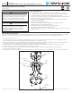
INSTALLATION (SEE FIGURE 1):
This fixture requires a 120V power source. Disconnect power at the source fuse or circuit breaker box before attempting installation. Ground the
fixture to avoid potential electric shock and ensure reliable start. Double-check all connections to be sure they are tight and correct.
1. Turn o power at the source.
2. Screw the mounting plate onto the junction box (standard 4” octagonal or round). Ensure the grounding screw is facing outward and the two
fixture mounting screws align horizontally with the desired orientation of the fixture’s canopy.
3. Pull the wires through the center of the installed mounting plate, then ax the grounding wires (yellow/green) to the grounding screw on the
mounting plate. Now, make supply wire connections to fixture (white to white, black to black).
4. Push the fixture on to the mounting plate, aligning the two fixture mounting screws with the two screw holes on the fixture’s canopy.
5. Use the canopy screw covers to securely fasten the fixture mounting screws.
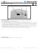
6. To ensure a weatherproof seal, use weatherproof silicone sealant around the edge of the canopy against the mounting surface.
7. Turn on power to test fixture operation.
8. To adjust color temperature of light, use the 3-cct slider switch in the center of the canopy to switch between 3000K, 4000K, and 5000K CCT.
WARNING
WARNING
FIGURE 1
Junction Box
Mounting
Plate
Fixture Mounting
Screws
Grounding Screw
Fixture
Canopy
Canopy
Screw Covers