
Installation Sheet

Page 2 of 2©2020 American Lighting, Inc. REV2047 www.AmericanLighting.com 11775 E. 45th Ave. Denver, CO 80239 Ph: 1-800-880-1180 Fax: 303-695-7633
TRULUX
®
HIGH DENSITY STATIC WHITE (IP54)24V
INSTALLATION INSTRUCTIONS
STLHD & HTLHD Series
Cut increments are clearly marked and should be
cut down the center, leaving copper conductor
pads exposed on both cut ends
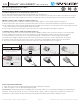
CUTTING & LINKING TRULUX® TAPE LIGHT (See Figures 2-7):
Do not exceed the maximum tape light run length of 16.4 feet in any single run.
Cut increments are clearly marked on the tape light (every 2.46” for STL series and every 1.51” for HTL series). Ensure an even cut
along the center of the copper conductors to ensure enough surface area is exposed for snap connector pins to pierce through.
MAKING A TAPETOTAPE CONNECTION SEE FIGURES 35:
1. Ensure the polarity of the conductors on the two pieces of tape light to be connected are aligned. See Figure 3.
2. Using a tape-to-tape snap connector, open both sides of the connector so the metal teeth inside are exposed. See Figure 4.
3. Peel a small portion of the protective backing from the tape light on the end to be connected, then insert cut tape light end so the
copper pad conductors are aligned with the metal teeth inside.
4. Close snap connector and use pliers to ensure the connector “snaps” through the tape light. See Figure 5.
TO MAKE A TAPETOWIRE CONNECTION SEE FIGURES 69:
1. Using a tape-to-wire snap connector, follow steps 1-4 from “Making a Tape-to-Tape Connection” above to connect tape light.
2. Ensure polarity of the conductors on the connected piece of tape light and the polarity of the wires align. See Figure 6.
3. Cut desired length of wire being sure to leave approximately 1/2’ on each end to be connected (wire not included).
3. Separate wires slightly so they fit in the grooves of the snap connector. There is no need to strip the wire. See Figure 7.
4. Insert the cut wire into the slots of the snap connector so the wire is aligned with the metal teeth inside. See Figure 8.
5. Close snap connector and use pliers to ensure the connector “snaps” through the wire. See Figure 9.
FIGURE 2 FIGURE 3
FIGURE 6 FIGURE 7 FIGURE 8 FIGURE 9
FIGURE 4 FIGURE 5
Red
Black
+24V DC
-
+24V DC
-
+24V DC
-
ADDITIONAL SAFETY MEASURES
1. Route and secure cords so that they will not be pinched or damaged in any way.
2. LEDs are bright. Do not look directly at lighted tape light.
Important Note: The National Electrical Code (NEC) does not permit cords to be concealed where damage to insulation may go
unnoticed. To prevent fire danger, do not run cord behind walls, ceilings, sots, or cabinets where it may be inaccessible for
examination. Cords should be visually examined periodically and immediately replaced when damage is noted.