
Installation Sheet

Page 1 of 4©2020 American Lighting, Inc. REV2034 www.AmericanLighting.com 11775 E. 45th Ave. Denver, CO 80239 Ph: 1-800-880-1180 Fax: 303-695-7633
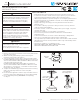
NIVO FLUSH MOUNT
120-
277V
INSTALLATION INSTRUCTIONS
NV5 & NV7 Series
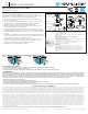
FIGURE 1
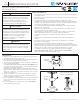
FIGURE 2
SAFETY INFORMATION
• Read all instructions before beginning; Save these instructions for future use.
• To reduce the risk of fire, electric shock, or injury to persons, pay close attention
to this manual and stay within its guidelines when using this product.
• LED Disc light installation requires knowledge of recessed lighting luminaires and
their electrical systems. If not qualified or uncertain, do not attempt installation:
contact a qualified electrician.
• Supply conductors (power wiring) connecting the fixture must be rated for a
minimum of 90°C.
• Do not make or alter any open holes in wiring enclosures, nor in any electrical
components during kit installation.
• Do not alter, relocate, or remove wiring, lamp holders, power supply, or any other
electrical component.
• This fixture is suitable for use in dry, damp, or wet locations.
• Do not use these products in luminaires located where elevated ambient
temperatures exist.
• To avoid electrical shock, do not turn on fixture with missing or damaged lens.
• There are no serviceable parts inside the fixture or LED module.
• Use only a mild soap and water with soft cloth to clean the fixture. Harsh chemicals
will damage the finish. Do not wipe the fixture with a rough cloth that may scratch
the finish or lens.
• This fixture is suitable for use in dimming circuits:
NV5-30-WH & NV7-30-WH: TRIAC/CL/ELV (FOR 120V ONLY)
NV5-0/10V-30-WH & NV7-0/10V-30-WH: 0-10V
These products may represent a possible shock or
fire hazard if improperly installed or attached in any
way. Products should be installed in accordance
with these instructions, current electrical codes,
and/or the current National Electric Code (NEC).
The electrical rating of this product is 120V AC
(NV5 & NV7) and 120-277V AC (NV5-0/10V & NV7-
0/10V), 60Hz. The installer must determine whether
the power supply is appropriate at the luminaire
prior to installation. To avoid possible electric
shock, be sure that power source is turned o at
fuse box and/or circuit breaker prior to attempting
installation or servicing of the fixture.
WARNING
WARNING
INSTALLATION:
1. Ensure power is disconnected at the source and any wall switches
are in the “o” position.
2. Ax the mounting plate directly to junction box using the
mounting screws provided. See Figure 1.
3. Connect supply wires to fixture wires, ensuring to match polarity.
For NV5-30-WH & NV7-30-WH (FOR 120V ONLY): Ground/Green to
Ground, Common/White to White, Hot/Black to Black, and insulate
connections with included wire nuts.
For NV5-0/10V-30-WH & NV7-0/10V-30-WH: Ground/Green to
Ground, Common/White to White, Hot/Black to Black, then 0-10V
wires Purple/+ to + and Grey/- to -, and insulate connections with
included wire nuts. See Figure 2.
4. Complete the installation by pushing the fixture into the mounting
plate so the clips fully seat into the center of the plate.
See Figure 2.
5. For wet location applications, seal the edge of the fixture where it
meets the ceiling surface with waterproof silicone (Not provided).
6. For use with battery back-up (NV7-BB-WH sold separately),
see Page 2.
Note: For 0-10V,
connect additional
low voltage wires.
White Wire
Black Wire
Ground Wire
Mounting
Plate
Use with a 4” octagonal or round junction box
with a minimum depth of 1-1/4” . Required distance
between mounting holes: 3-1/2”.
Do not attempt to alter for other sizes or purposes.
WARNING