
Installation Sheet

Page 2 of 4©2020 American Lighting, Inc. REV2034 www.AmericanLighting.com 11775 E. 45th Ave. Denver, CO 80239 Ph: 1-800-880-1180 Fax: 303-695-7633
NIVO FLUSH MOUNT
120-
277V
INSTALLATION INSTRUCTIONS
NV5 & NV7 Series
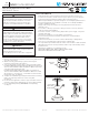
BATTERY BACK-UP INSTALLATION (Figures 3-5):
This battery back-up (NV7-BB-WH) is rated for an input voltage of
100-277V AC, 50-60Hz and produces an output power of up to 20W. It is
intended for use with NV7-30-WH or NV7-0/10V-30-WH only.
1. Ensure power is disconnected at the source and any wall switches
are in the “o” position.
2. Connect supply wires to battery back-up, ensuring to match polarity
(Ground/Green to Ground, Common/White to White, Hot/Black to
Black) and insulate connections with included wire nuts.
3. Ax the battery back-up directly to the junction box via two screw
holes on the back of the battery back-up.
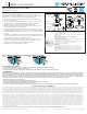
4. Connect supply wires from battery back-up to fixture wires, ensuring
to match polarity (Ground/Green to Ground, Common/White to White,
Hot/Black to Black and Brown) and insulate connections with included
wire nuts.
5. Complete the installation by pushing the fixture into the battery back-
up so the clips fully seat into the center. Ensure all 4 clips are oriented
so they grip onto the edge of the battery back-up.
6. For wet location applications, seal the edge of the fixture where it
meets the ceiling and where the battery back-up meets the fixture
with surface with waterproof silicone (Not provided).
7. See Figure 5 for battery back-up operation.
5-YEAR LIMITED PRODUCT WARRANTY
This product is warranted to be free from defects in material and workmanship for a period of five (5) years from the date of purchase. Products that prove to be defective during this period
will be either repaired (i.e. replacement of defective electronics, defective parts of the fixture housing, lens, wiring, switching or lamp sockets; excluding the lamp) or replaced, at the discre-
tion of American Lighting, Inc claims for defective products must be submitted to the retail location from which the product was purchased withing the warranty period. Upon submission
of proper return claim documentation and product to American Lighting, Inc by the retailer, American Lighting, Inc reserves the right to inspect the product for misuse or abuse. Claims for
indirect or consequential damages or for product that, in American Lighting, Inc’s opinion has bee misused, will be denied. This is a warranty of product reliability only and not a warranty
of merchantability or fitness for a particular purpose. American Lighting, Inc shall have no liability whatsoever in any event for payment of incidental or consequential damages, including,
without limitations, installation costs and damages for personal injury and property. These products may represent a possible shock or fire hazard if improperly installed or altered in any
way. This warranty applied only to product that has been properly installed in accordance with instruction sheet and current local codes and/or the National Electrical Code. Warranty does
not apply to any product that has been improperly installed or in situation where components have been altered in any way. This warranty: (1) excludes expendable parts including but not
limited to light bulbs, batteries; (2) carries a 2-year finish warranty protecting finish against tarnishing, flaking, and discolorations; (3) shall be void if this lighting fixture is not installed in the
U.S.A.; and (4) does not cover any losses, labor, injuries to persons/property or costs. This warranty does give you specific legal rights and you may have other rights, which vary from state
to state, Be careful, it is recommended that installation be done by a qualified professional; the purchaser has sole responsibility for proper installation in compliance with all state and local
code requirements. Seller’s employees are not qualified to advise you on the use of this Merchandise. Any oral representation(s) made will not be binding on seller or its employees. The
rights under this limited warranty are to the original purchaser of the Merchandise and may not be transferred to any subsequent owner. This limited warranty is in lieu of all warranties,
expressed or implied including warranties or merchantability and fitness for a particular purpose. Seller shall not be liable for any special, incidental, or consequential damages. The sold
exclusive remedy against the seller will be for the replacement of any defects as provided herein, as long as the seller is willing or able to replace this product or is willing to refund the
purchase price as provided above.
For questions/comments, technical assistance, or repair parts - Please call toll free at 1-800-285-8051 (M-F 8am-5pm), CST)
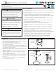
EVERFINE GONIOPHOTOMETERS SYSTEM TEST REPORT Page 1 Of 10
LUMINAIRE PHOTOMETRIC TEST REPORT
NAME: dl-7a-15fc
SPEC.:15W
MFR.: LiBo
TYPE:0
DIM.:
SUR.:
WEIGHT:
SERIAL No.:
Shielding Angle:
Test:U:120.00V I:0.0828A P:9.7927W PF:0.9857 Freq:0Hz Lamp Flux:710.939x1 lm
0
30
60
90
120
150
-/+180
-150
-120
-90
-60
-30
UNIT:cd
C0/180,153.8
UNIT:cd
C30/210,153.6
UNIT:cd
C60/240,153.6
UNIT:cd
C90/270,153.5
AVERAGE BEAM ANGLE(20%):153.6 DEG
0
50
100
150
200
250
LUMINOUS INTENSITY DISTRIBUTION DIAGRAM
C0 PLANE ISOLUX DIAGRAM (UNIT:lx)
MH(m)
2
3
4
5
6
7
8
9
10
11
12
0.0 4.0 8.0
S(m)
35.0
29.0
23.0
18.0
12.0
5.90
4.70
2.90
2.30
1.80
DATA OF LAMP PHOTOMETRIC DATA Eff: 72.60 lm/W
MODEL
NOMINAL POWER(W)
RATED VOLTAGE(V)
NOMINAL FLUX(lm)
LAMPS INSIDE
TEST VOLTAGE(V)
Imax(cd)
LOR(%)
TOTAL FLUX(lm)
CIE CLASS
up(%)
down(%)
η
η
S/MH(C0/180)
S/MH(C90/270)
UP,DN(C0-180)
UP,DN(C180-360)
CIBSE SHR NOM
CIBSE SHR MAX
η
η
30
120
710.939
1
120.0
232.4
100.0
710.94
DIRECT
2.5
97.5
1.28
1.27
1.3,48.3
1.2,49.1
1.25
1.35
C Range: 0 - 360DEG
C Interval: 15.0DEG
Range: 0 - 180DEG
Interval: 1.0DEG
γ
γ
Test Speed: HIGH Test System:EVERFINE GO-SPEX500_V1 SYSTEM V2.0.402
Temperature:25.3DEG Humidity:65.0%
Test Distance:3.010m [K=1.0000]Operators:
Test Date:19 December 2019 Remarks:
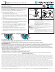
EVERFINE GONIOPHOTOMETERS SYSTEM TEST REPORT Page 1 Of 10
LUMINAIRE PHOTOMETRIC TEST REPORT
NAME: DL-7A-10FCh
SPEC.:15W
MFR.: LiBo
TYPE:0
DIM.: 1
SUR.:
WEIGHT:
SERIAL No.:
Shielding Angle:
Test:U:120.00V I:0.1205A P:14.370W PF:0.9935 Freq:59.98Hz Lamp Flux:1254.09x1 lm
0
30
60
90
120
150
-/+180
-150
-120
-90
-60
-30
UNIT:cd
C0/180,150.2
UNIT:cd
C30/210,150.2
UNIT:cd
C60/240,150.3
UNIT:cd
C90/270,150.3
AVERAGE BEAM ANGLE(20%):150.2 DEG
0
90
180
270
360
450
LUMINOUS INTENSITY DISTRIBUTION DIAGRAM
C0 PLANE ISOLUX DIAGRAM (UNIT:lx)
MH(m)
2
3
4
5
6
7
8
9
10
11
12
0.0 4.0 8.0
S(m)
66.0
55.0
44.0
33.0
22.0
11.0
8.80
5.50
4.40
3.30
DATA OF LAMP PHOTOMETRIC DATA Eff: 87.27 lm/W
MODEL
NOMINAL POWER(W)
RATED VOLTAGE(V)
NOMINAL FLUX(lm)
LAMPS INSIDE
TEST VOLTAGE(V)
Imax(cd)
LOR(%)
TOTAL FLUX(lm)
CIE CLASS
up(%)
down(%)
η
η
S/MH(C0/180)
S/MH(C90/270)
UP,DN(C0-180)
UP,DN(C180-360)
CIBSE SHR NOM
CIBSE SHR MAX
η
η
30
120
1254.09
1
120.0
429.4
100.0
1254.1
DIRECT
1.9
98.1
1.24
1.25
1.0,49.1
0.9,49.0
1.25
1.35
C Range: 0 - 360DEG
C Interval: 15.0DEG
Range: 0 - 180DEG
Interval: 0.5DEG
γ
γ
Test Speed: MEDIUM Test System:EVERFINE GO-SPEX500_V1 SYSTEM V2.0.402
Temperature:25.3DEG Humidity:65.0%
Test Distance:3.010m [K=1.0000]Operators:
Test Date:19 December 2019 Remarks:
PHOTOMETRIC DISTRIBUTION SHOWING INTENSITY (Candelas):
NV5 NV7
FIGURE 3
FIGURE 4
FIGURE 5
Battery
Back-up
Junction
Box
Mounting
Screws
Emergency LED Indicator Colors/ Function
Green: Emergency function working with battery
Green Flashing: Lighting flashing, no power for the battery,
recharging for the battery
O: Emergency function is o , the ceiling working with normal
power supply
Emergency Battery Indicator Color and Functions
Red: Battery is charging
Green: Battery at full charge
Red Flashing: Check system-possible battery replacement needed
or system maintenance required
O: Indicates a power outage when the battery backup unit is in
emergency mode the LED indicator will be O
Minimum Charge Time: 14hours
Test Button
While main power is on: A quick press of the test button(<3
seconds), simulates the “main power outage” or emergency
mode”. The light fixture will come in this case. It will be running on
battery power.
While in Emergency Status (mains power outage): Pressing test
button for <6 seconds shuts o the unit; press again to turn it
back on.
FCC Compliance Statement
This device complies with part 15 of the FCC Rules. Operation is subject to the following two conditions:
1. This device may not cause harmful interference, and
2. This device must accept any interference received, including interference that may cause undesired operation.
FCC WARNING
This equipment has been tested and found to comply with the limits for a Class B digital device, pursuant to Part 15 of the FCC Rules. These limits are designed to
provide reasonable protection against harmful interference in a residential installation. This equipment generates, uses and can radiate radio frequency energy
and, if not installed and used in accordance with the instructions, may cause harmful interference to radio communications. However, there is no guarantee that
interference will not occur in a particular installation. If this equipment does cause harmful interference to radio or television reception, which can be determined by
turning the equipment o and on, the user is encouraged to try to correct the interference by one or more of the following measures:
• Reorient or relocate the receiving antenna.
• Increase the separation between the equipment and the receiver.
• Connect the equipment into an outlet dierent from that to which the receiver is connected.
• Consult the dealer or an experienced radio/TV technician for help.
Any changes or modications not expressly approved by the party responsible for compliance could void the user’s authority to operate the equipment.