
Installation Sheet

Page 2 of 2©2021 American Lighting, Inc. REV2103 www.AmericanLighting.com 11775 E. 45th Ave. Denver, CO 80239 Ph: 1-800-880-1180 Fax: 303-695-7633
TRULUX
®
SINGLE COLOR (IP54)24V
INSTALLATION INSTRUCTIONS
STL, HTL, SPTL, SPTLX, and VTL Series
Cut increments are clearly marked and should be
cut down the center, leaving copper conductor
pads exposed on both cut ends
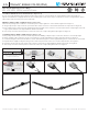
CUTTING & LINKING TRULUX® TAPE LIGHT (See Figures 2-7):
Do not exceed the maximum tape light run length in any single run. Cut increments are clearly marked on the tape light (see
Layout Considerations on Page 1). Ensure an even cut along the center of the copper conductors to ensure enough surface area is
exposed for snap connector pins to pierce through.
MAKING A TAPETOTAPE CONNECTION (See Figures 3-5):
1. Ensure the polarity of the conductors on the two pieces of tape light to be connected are aligned. See Figure 3.
2. Using a tape-to-tape snap connector, open both sides of the connector so the metal teeth inside are exposed. See Figure 4.
3. Peel a small portion of the protective backing from the tape light on the end to be connected, then insert cut tape light end so the
copper pad conductors are aligned with the metal teeth inside.
4. Close snap connector and use pliers to ensure the connector “snaps” through the tape light. See Figure 5.
TO MAKE A TAPETOWIRE CONNECTION (See Figures 6-9):
1. Using a tape-to-wire snap connector, follow steps 1-4 from “Making a Tape-to-Tape Connection” above to connect tape light.
2. Ensure polarity of the conductors on the connected piece of tape light and the polarity of the wires align. See Figure 6.
3. Cut desired length of wire from the 15ft reel of wire included being sure to leave approximately 1/2’ on each end to be connected.
3. Separate wires slightly so they fit in the grooves of the snap connector. There is no need to strip the wire. See Figure 7.
4. Insert the cut wire into the slots of the snap connector so the wire is aligned with the metal teeth inside. See Figure 8.
5. Close snap connector and use pliers to ensure the connector “snaps” through the wire. See Figure 9.
FIGURE 2 FIGURE 3
FIGURE 6 FIGURE 7 FIGURE 8 FIGURE 9
FIGURE 4 FIGURE 5
Red
Black
+24V DC
-
+24V DC
-
+24V DC
-
FIGURE 10 FIGURE 11