
Installation Instructions

2
L-C2-360
REV 3 - 1812041115
Drawer
support
Side View
Drawer
Front
For proper installation, be sure to use the correct cutout
dimensions as specifi ed for your model number. Locate your
model on the following pages for dimensions, and reference the
cut-out diagram of your unit for proper orientation.
Important: Doors and drawers are supplied with 8 screws for
installation. If installing into a concrete island, pilot
holes are required.
Important: When installing in an AFD GFRC Island, use the
bracket and screws provided with the island.
DOOR
Slide in and fasten the unit securely into the island enclosure using
the supplied hardware through the installation screw slots in the top
and bottom of the unit.
For doors with propane tank trays:
To use, simply open the door, pull out the sliding cylinder tray, place
your cylinder on the tray and push the tray back in. The cylinder is
now ready for connection to your grill.
Important: Refer to any additional instructions included with
your door for the required installation method of
propane tank cylinders.
DRAWER
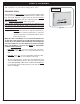
Before installing your drawer, remove the drawer from its base by
completely pulling it out. Release the drawer from the drawer slides
by pressing the black lever down on the right side, and up on the left
side (Fig 2-3). Then pull outward on the drawer until it comes free of
the runners.
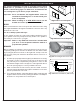
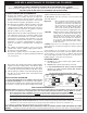
1. In order to properly support the weight of your drawer, it is necessary
to provide a secure, level surface in the rear of the unit (see
Fig
2-4
). This may be accomplished by using bricks, 2 X 4’s, etc. Be
sure that the height of this rear support is
1
/
8
" higher than that of
the front opening support, so that your drawer sits level.
2. Slide in and fasten the unit securely into the island enclosure
using the supplied hardware through the installation screw slots
in the top and bottom of the unit.
3. To re-attach the drawer; extend the drawer slides completely and
align the drawer into the slides, pushing the drawer closed. Open
the drawer to verify that it has locked in place.
Fig. 2-3 Releasing drawer from slides
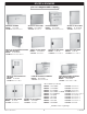
Fig. 2-1 Door cut-out diagram
H
E
I
G
H
T
DEPTH
WIDTH
WIDTH
H
E
I
G
H
T
Fig. 2-4 Drawer Installation (Side View)
Fig. 2-2 Drawer cut-out diagram
INSTALLATION GUIDELINES
INSTALLATION GUIDELINES