
L Series Quick Start Guide

6-Propane and Natural Gas Safety
IMPORTANT: READ AND FOLLOW ALL WARNINGS PROVIDED WITH THE PROPANE-GAS CYLINDER.
READ ALL SAFETY INSTRUCTIONS AND WARNINGS REGARDING THE USE OF PROPANE GAS FOUND
IN YOUR OWNER’S MANUAL. FOR NATURAL GAS READ ALL SAFETY INSTRUCTIONS AND WARNINGS
FOUND IN YOUR OWNER’S MANUAL.
7-Routine Maintenance
Your grill must be serviced and maintained properly to ensure optimal performance, appearance, and safety. Clean your grill before and
after each use. Additionally, a deep clean of the entire grill and all its components be performed twice a year (or as needed depending
on use). See owner’s manual for details.
REV 2 - 1901141405
L-C2-482
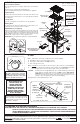
4-Grill Setup
Parts Placement Checklist
Place the following items according to their position and orientation
in Fig. 4-1:
Vaporizer panels, cooking grids, and warming rack.
Leave pre-installed burners in place to maintain proper alignment.
Vaporizer Panels
Place the vaporizer panels directly onto the studs on the burners. The
panels allow heat from the burners to be evenly directly throughout
the cooking area.
Cooking Grids
Place the cooking grids (over the burners) onto the grid frame.
Warming Rack
The warming rack comes pre-installed. Remove zip ties before use.
Consult the owner’s manual to remove or replace.
Shelf/Sideburner (if equipped)
Align the four (4) holes in the shelf with the four (4) holes in the side
of the cart while aligning and engaging the burner venturi with the
orifice (Fig. 4-2). Insert the four (4) screws (provided) into the holes and
tighten. Make the igniter wire connection as shown in Fig. 4-2. Open
sideburner lid, set cap on burner, and set grid into shelf.
IMPORTANT: See your grill owner’s manual for complete installation
details.
Fig. 4-1
Cooking Grid
Vaporizer panel
(not with IR)
Main
burner*
Warming
rack
Rotisserie kit
(if equipped)
Sideburner shelf
(if equipped)
Note: For infrared burner (IR) equipped
grills; see detailed instructions
included in your owner’s manual.
Power
supply
Drip tray
Light
switch
Grill lights
(not shown)
Ignition
switch
Backburner
(if equipped)
Replacement parts can
be ordered from your
local AOG dealer.
Side Burner
Fig. 5-2
5-Test
WHEN OPERATING THIS
GAS APPLIANCE, ALL
INSTRUCTIONS AND
WARNINGS MUST BE
OBSERVED. FAILURE TO DO
SO MAY RESULT IN A FIRE
OR EXPLOSION CAUSING
PROPERTY DAMAGE, BODILY
INJURY, OR DEATH.
Note: Grill must be connected to 120VAC power for electronic lighting.
1. Open lid(s) or remove cover(s) from burner(s) to be lit.
2. Turn all gas control knob(s) to their OFF position(s).
3. Turn on the gas at its source.
Note: DO NOT turn on more than one valve at a time for either electronic or manual lighting.
4. Depress the control knob for the burner to be lit and turn it to the HI LIGHT position, then
press the ignition button. Once the burner lights, release the ignition button.
CAUTION: If a burner does not light within five (5) seconds of turning on the control
knob, depress the knob and turn it to the OFF position. WAIT FIVE (5)
MINUTES before repeating step 4. If you smell gas, follow the instructions on
the cover of the grill owner’s manual. If the burners still do not light after several
attempts, refer to the grill owner’s manual for manual lighting.
5. Repeat step 4 for each additional burner to be lit.
30" and 36" model controls
Center main burner
control knob
Left
main burner
control knob
Right
main burner
control knob
Backburner
control knob
(if equipped)
Control panel
screw(s)
Drip
tray
Ignition
switch
Sideburner
control knob
(if equipped)
The light switch is push button operated,
and is located on the right side of the
control panel (see Fig. 5-2). It controls
the power to all lights.
*
The burner
ports and carry-
over ports must
be kept clean to
ensure proper
ignition and
operation.
Light
switch
‡
‡
For your convenience and safety;
when the control knob is turned to
the ON position, the gas flow indicator
will change from blue to red. (Red
indicates gas flow.) See Fig. 5-1.
Fig. 5-1 - Burner valve control knob
OFF
HI
LIGHT
LOW
T O
TURN OFF
T O TURN ON
Read setting
here
HIGH to
LIGHT
Read setting here
(OFF position shown)
To Turn OFF
To Turn ON
Use
HI (high)
to light
Press
knob in
to turn
Gas Flow
Indicator
Screws
Air shutter
Orifice
Igniter wire
Fig. 4-2
Venturi
Connect
Screws
Air shutter
Orifice
Igniter wire
Fig. 4-2
Venturi
Connect