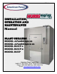
REV. C Cooler is Better!TM INSTALLATION, OPERATION AND MAINTENANCE Manual BLAST CHILLERS MODEL AP40BC250-12 MODEL AP40BC250-2-12 MODEL BCCP-1 MODEL BCCP-2 MODEL BCIP American Panel Corporation 5800 S.E. 78th Street, Ocala, Florida 34472-3412 Phone: (352) 245-7055 Fax: (352) 245-0726 E-mail: service@americanpanel.
Thank you, and congratulations on your purchase of an American Panel blast chiller. We take great pride in engineering and manufacturing each of our products. With the goal of providing the highest accuracy and quality possible, our state-of-the-art manufacturing and quality control facility enables us to continually explore new technologies so that we can provide you with the finest equipment in the industry.
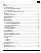
INDEX Index Index ....................................................................................................................................................................................... 1 A. Introduction ......................................................................................................................................................................... 2 A.1. Controller Features................................................................................................
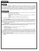
INTRODUCTION A. Introduction The Models AP40BC250-12, AP40BC250-2-12, BCCP-1, BCCP-2, and BCIP Blast Chillers are used to rapidly chill cooked foods to temperatures suitable for storage in a refrigerator. Blast chillers are sophisticated refrigeration machines capable of lowering the core temperature of most foods from 160°F to 38°F in less than two hours.
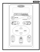
CONTROLLER 3
INSTALLATION B. Installation American Panel Corporation equipment has been shipped in a package designed to sufficiently protect from damage under normal shipping circumstances. Upon receiving the shipment, carefully inspect the package for visible damage and check the number of packages against the Bill of Lading. Notify the carrier immediately of any shortage or damage to your shipment. Claims must be filed promptly with the carrier.
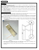
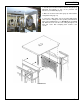
INSTALLATION B.2. Single Unit Installation AP40BC250-12 And BCCP-1 B.2.1. Install Coil Assembly Frame 1. Insert the coil assembly frame into the door latch side of the box with the filter facing the interior of the box (see DRAWING # 2). Push the assembly tight to the side wall leaving ¼” space at the front and rear panels. Note the three holes on the stainless steel angle frame (at the top of the horizontal cross brace on the vertical surface at the back of the frame). Drill 1/8” pilot holes.
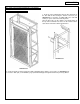
INSTALLATION B.2.2. Install Fan Assembly Frame 1. Insert the fan assembly frame into the door hinge side of the box with the fans facing the interior of the box (see DRAWING # 4). Push the assembly tight to the side wall leaving ¼” space at the front and rear panels. Note the three holes on the stainless steel angle frame (at the top of the horizontal cross brace on the vertical surface at the back of the frame). Drill 1/8” pilot holes into the back panel of the box. 2.
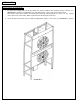
INSTALLATION 3. Seal the spaces between frames and side box panels by tightening the butterfly ¼” nuts on the provided seal brackets (see PHOTO #3 page 8). 4. Make the electrical connections (page 8) and install the refrigeration unit (page 13). 5. Lower the ceiling panel over the Coil Assembly Frame and secure the ceiling to the fans top filler panel with 8/32” bolts in the predrilled holes (see DRAWING # 5 & PHOTO #2).
INSTALLATION PHOTO #3 B.2.3. Electrical Connections All power cables inside the cabinet, with the exception of door / window heater and door switch cables (see PHOTO #4, page 10), are provided with twist and lock plugs and connectors. All cables, plugs, and connectors are color coded (see Color Code Chart on page 9). Connect the plugs and connectors of the same code color (see PHOTO #5, page 10). According to the color code chart, the orange coded cable is for the door / window heater.
INSTALLATION DRAWING #6 NOTE: Route the micro-switch (B) wires through the wall and bring them inside the box at approx. 6” above the door. Insulate the wall hole (s) with silicone or grommets. Take precaution to protect the heater wires inside the door frame.
INSTALLATION PHOTO #4 PHOTO #5 10
INSTALLATION PHOTO #6 B.3. Double Unit Installation AP40BC250-2-12, BCCP-2, And BCIP Installation procedures are similar with the ones for the single unit. Each of the two evaporators is fed by one condensing unit. Both single units installed in a double box are controlled by one electronic controller. The difference is made by the double number of power cables and air probe cables. The two frames to be installed by the control board are marked # 1.
INSTALLATION PHOTO #7 Door magnetic switch on the left; Magnet on the right PHOTO #8 12
INSTALLATION PHOTO #9 C. Refrigeration Unit Installation C.1. Preparation 9 9 9 9 9 9 Check the integrity of the unit once it is unpacked Check to make sure the floor is leveled Check that the available power supply corresponds to the ratings on the unit’s nameplates and correctly rated electrical protection is provided. If additional refrigerant should be needed, be certain to use the correct type. Make certain that adequate drainage is provided.
INSTALLATION electrical power supplies. Each wire must be connected to its corresponding terminal. The ground wire must be connected to an efficient ground terminal. C.3. Refrigeration Lines Installation Follow the steps below to assure a proper installation. 1. Minimum pipe inclination has to be provided. CONDENSING UNIT 2. Make sure you place the fastening brackets on insulated piping. 3. Provide air tight welding. 4. Create the vacuum and load the line. 5. 6. 7. 8. Check for leaks.
INSTALLATION Distance (ft.) 16 32 48 64 80 Number of Pipe Supports 2 3 5 7 9 C.3.1. Installation At The Same Level If the condensing unit is going to be installed at the same level with the cabinet, follow the instructions in the FIG #5 FIG # 5 C.3.2. Installation At Different Levels If the remote condensing unit is installed at a higher level than the cabinet (FIG #6) insert a siphon in the return line at every 6 ft. of difference in height.
INSTALLATION The specified piping diameters (see chart below) from the remote condensing unit to the cabinet is adequate for a separation of up to 60 feet. For greater distances, contact the factory for instructions. Supply Line Intake Line Diameter of Copper Piping ½” 1 1/8” **Note: The insulation used on the piping must be of high quality and must have closed cells. CONDENSATE DRAINAGE CONNECTION It is important that condense from the evaporator is properly drained.
PROGRAMMING D. Programming The Controller WARNINGS! Read and carefully follow all of the instructions in this manual before attempting to install this equipment. Installation must be performed by a qualified Service Agency approved and authorized by American Panel Corporation. Doing otherwise may void the warranty. Any changes made to the equipment without authorization from the factory will void the warranty. PREPARATION 9 9 9 9 Check the integrity of the unit once it is unpacked.
PROGRAMMING D.3. Programming Modes All American Panel Corporation blast chillers are initially programmed at the factory. These settings may be considered standard for AP40BC250-12, AP40BC250-2-12, BCCP-1, BCCP-2, and BCIP units. However, the customer may change any of these settings as indicated by necessity. There are two programming modes to be covered: Initial Programming - settings like year, month, date, time, and several other parameters.
PROGRAMMING The controller will ask the operator to enter the access code. Press, in order and within Æ 20 seconds, the following combination Æ . When done, confirm by . pressing Note: If the entered access code is not correct, the controller will ask the operator to re-enter the code. Wait five seconds and then re-enter the access code. If the correct code is entered, the controller will give a short beep and display the message: To skip press .
PROGRAMMING and buttons to scroll to the baud rate of your computer. Most computers Use use 38400 baud rate. Press when done. If “PC CONNECTION” is set to “NO”, the controller will jump to the “PRINTER CONNECTION” screen. If “PC CONNECTION” is set to “YES”, the controller will ask you to select the unit’s ID number. To change the ID number for a particular chiller, use when done. and buttons. Press Note: If more than one chiller is connected to the PC, each chiller must have a different ID number.
PROGRAMMING The Initial Programming is now complete. After five seconds the display will show “OFF”. Until then no command is available. D.5. Parameter Programming The versatility of the control panel allows the operator to choose between five cycles. Two blast chilling modes: Automatic and Manual, and three special cycles: UV, Defrost, and Print. All of these cycle’s parameters have to be carefully programmed. FOR AN EXPLANATION OF THE BLAST CHILLING MODES REFER TO CHAPTER D.1. PAGE 17 OF THIS MANUAL.
PROGRAMMING and buttons to increase or decrease the high air temperature (cut in) Use setting for the first part of the cycle. Press when done. and buttons to increase or decrease the low air temperature (cut out) Use setting for the second part of the cycle. Press when done. and buttons to increase or decrease the high air temperature (cut in) Use setting for the first part of the cycle. Press when done.
PROGRAMMING and buttons to increase or decrease the low air temperature (cut out) Use setting for the second part of the cycle. Press when done. Note: The second part of the cycle is the holding mode. and buttons to increase or decrease the high air temperature (cut in) Use setting for the second part of the cycle. Press when done. and buttons to increase or decrease the amount of time the controller is Use going to keep the unit in the first part of the manual cycle.
PROGRAMMING D.5.4. Parameter Programming For UV Cycle The controller will ask the operator to choose an operating cycle. Press parameters for the UV cycle. to set the and buttons to increase or decrease the amount of time in which the Use Germicidal Lamp will be on. Press when done. Note: The UV cycle is an optional feature. Program the UV cycle only if the unit is equipped with a Germicidal Lamp. D.5.5.
PROGRAMMING D.6.1. Setting The Food Probe Alarms Make sure the control panel is in OFF mode. Press and hold same time, for five seconds. and , at the The display will show: and buttons to increase or decrease the desired end temperature of the Use food. The red food probe alarm will go off if the food temperature goes below this point. Press when done. and buttons to increase or decrease the high temperature point.
PROGRAMMING Use and name, press buttons to scroll to the desired recipe number. To edit the recipe . and buttons to scroll thru the characters. Press Use character or to add characters. Press to save the change and to move to the next recipe number. To exit recipe name programming mode, press before pressing Note: Do not press character press to move to the next . . The changes for that particular recipe number will not be saved. To delete a . E.
PROGRAMMING 1. It is possible to insert the ribbon cartridge if there is already paper in the printer. 2. Hold the cartridge at each end with thumb and forefinger and slide it over the paper and into the printer compartment be sure the paper goes between the ribbon cartridge and the ink ribbon. If you get ribbon ink on the printer case, wipe it off immediately as once it dries it is difficult to remove. E.7.
OPERATING F. Operating And Maintaining The Unit F.1. Panning And Loading Panning 1. Standard pan depth is 2-1/2”. Other depths can be used but are not recommended as their use would require an increase in the cycle time. 2. Stainless steel or aluminum pans are recommended. Plastic containers will increase the chilling time by 10%. 3. Crockery or stainless cylinders, 6”dia. and 10” max. height, are acceptable. 4. Slack filled cryovac bags can be used if placed on wire shelves. 5.
OPERATING F.2. Operating Note: The instructions below contain screens with the exact messages displayed by the controller during operating procedure. Follow the notes located to the right of these screens. F.2.1. Automatic Cycle Make sure the controller is in OFF mode. Press to start the unit. The controller will display the greeting message. The controller asks the operator to choose an operating cycle. Choose between automatic, manual, defrost, UV, and print cycle. To start the automatic cycle press .
OPERATING recipes into the controller’s memory. To skip these steps press enter for each probe color. and buttons to scroll thru the preset recipe names and numbers. Press To set the recipe for each probe use when done to move to the next probe. After the recipes have been set for all four probes the controller will alternately display the food temperature screen and the air temperature screen Note: For an explanation of the displayed parameters see Fig.8, page 28. To start the cycle press .
OPERATING to exit the defrost cycle. Press F.2.4. UV Cycle Make sure the unit is on and the display shows: The controller asks the operator to choose an operating cycle. Choose between automatic, manual, defrost, UV, and print cycle. To start the UV cycle press Press . to start the cycle. The controller will display the remaining time of the cycle. At the end of the cycle the controller will beep and display the message: Press to exit the UV cycle. F.2.5.
OPERATING F.2.6. Error Messages And Troubleshooting Problems beyond the routine maintenance would probably involve the refrigeration system or the control system. It is recommended to contact the factory for assistance if this should occur. Note that the warranty would be voided if these components are serviced by other than trained technicians approved by the manufacturer. Here is an error message and troubleshooting procedure list that may occur. Check the doors are tightly closed.
MAINTENANCE F.3. Maintenance And Cleaning Warnings: 1. Read all the instructions before you attempt to operate the equipment. 2. Always disconnect the unit from the power source before attempting any service or maintenance. 3. Repairs should be performed by a qualified service agency approved by American Panel Corporation. 4. Any changes made to the equipment without the written authorization from the factory will void the warranty. Daily Cleaning: 1. Before starting, remove the plug from the wall.
WARRANTY G. Standard Warranty 2) AMERICAN PANEL CORP. 5800 S.E. 78th Street, Ocala, Florida 34472-3412 American Panel Corporation products are warranted to the original user installed within the United States and Puerto Rico to be free from defects in materials and workmanship under normal use and service for the applicable period shown in the chart below. NOTE: This Warranty does not apply to altered or misused parts.
APPENDIXES Appendixes Appendix 1 Settings Record for AP40BC250-12, AP40BC250-2-12, BCCP-1, BCCP-2, and BCIP The first column shows typical settings. These are in accord with the settings given in this manual for programming. If your own experience with your own recipes indicates the need for different settings, it is suggested that you record these settings on this form, along with the resulting temperatures and a description of the product. Chapter Reference AUTO Item Recommended ºF L. AIR H. AIR L.
APPENDIXES Appendix 2 Electrical Schematic 1 36
APPENDIXES Appendix 3 Electrical Schematic 2 37
APPENDIXES Appendix 4 Parts List Part Number Description 990066 991011 991007 994085 Solenoid Coil Assembly for EVR 208/240 50/60Hz 17.5W Junc. Solenoid Valve EVR6 Excl. Coil 1/2 ODF Filter Drier 1/2" SAE Condensing Unit 991005 990042 990083 992025 992001 991006 990047 990076 990049 991012 990060 990059 990074 990075 990002 990018 990029 990030 990031 990032 990033 990034 990035 990036 1098 990052 990013 Evaporator Coil (Stainless Steel Frame) Heaters, Coil Tblr.
APPENDIXES Appendix 5 Ordering Printer Supplies (Ribbon & Paper) Replacement paper and ribbons for the printer supplied with your blast chiller can be ordered from a local distributor of Weigh-Tronix supplies. To locate a distributor near you: If you have access to the internet: Go to www.wtxweb.com Click on Sales & Service Click on Dealer Locator Enter your zip code or city / state If you do not have access to the internet: Call American Panel Corp.
American Panel Corporation 5800 S.E. 78th Street, Ocala, Florida 34472-3412 Phone: (352) 245-7055 Fax: (352) 245-0726 E-mail: service@americanpanel.