
Technical information
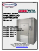

INSTALLATION
8
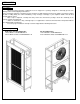
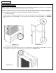
B.2. Initial Cabinet Preparation
Note: Refer to the assembly drawing attached to the back of this manual to determine the location of the components
inside the cabinet, the location of the drain line and the location of the controller.
Check if the cabinet was provided with penetrations to accommodate the refrigeration pipes (2-1/2” hole), the drainpipe (1-
1/2” hole), and the controller (7-1/2” x 3-1/2”). If the cabinet was provided with penetrations proceed with the installation of
the coil assembly frame (section B.3 of this manual). Otherwise follow the procedure below:
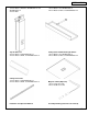
1. Cut hole for drainpipe
Measure location of drainpipe on drain pan where it will extend behind the Coil Assembly Frame (see DRAWING
B.2.1). Properly cut a corresponding 1 ½” hole in the rear corner panel to receive the drainpipe (see DRAWING
B.2.2).
DRAWING B.2.1 DRAWING B.2.2
2. Cut hole for the refrigeration lines
Measure and locate the refrigeration lines on the coil assembly frame and properly drill corresponding 2 ½” holes in
the ceiling side or rear panels to accommodate 1 1/8” and ½” pipes (see DRAWING B.2.3).
DRAWING B.2.3