® w w w.apc.com APC 3-in-1 Wireless Mobile Router User’s Manual 990-2149 Copyright © 2005 American Power Conversion. All rights reserved. American Power Conversion and TravelPower are registered trademarks of American Power Conversion. All other trademarks are the property of their respective owners.
© Copyright 2005 American Power Conversion Corporation. American Power Conversion Corporation is headquartered in West Kingston, Rhode Island. American Power Conversion, the American Power Conversion logo, and other American Power Conversion product name(s) are trademarks or registered trademarks of American Power Conversion Corporation in the United States and/or other countries.
Contents Preface v Intended Audience v Contents of this Manual v Conventions and Typefaces Used in This Manual v Copyright v Software v Regulatory Approvals vi CE Standards vi CE Marking Warning vi Compliance Statement vi Disclaimers vi Trademarks vi Additional Information vi Chapter 1: Introduction 1 Features 1-1 General 1-1 Wireless 1-1 Router Mode Features 1-1 Package Contents 1-2 Physical Features 1-2 Modes 1-3 Access Point (AP) Mode 1-4 AP/Router Mode 1-4 Config Mode 1-5 Client Mode 1-5 Chapter 2:
Chapter 4: Configuring the Router for AP/Router Mode 4-1 Connecting in AP/Router Mode 4-1 Using the AP/Router Setup Screen 4-2 The Wireless Security Screen 4-4 Security System: WEP 4-4 Security System: WPA-PSK 4-5 The Trusted Wireless Stations Screen 4-6 The Ethernet (WAN) Port Configuration Screen 4-7 Connection Type: Travel Mode (Hotel) 4-7 Connection Types: PPPoE, PPTP, L2TP, and No Login 4-8 The Ethernet (WAN) Port Status 11 Fixed/Dynamic IP Address 4-11 Connection Status - PPPoE (Point-to-Point Proto
APPENDIX A. TROUBLESHOOTING AND MAINTENANCE A-1 General Problems A-1 Wireless Access — AP or AP/Router Mode A-1 Router Mode A-2 APPENDIX B. ABOUT WIRELESS LANS B-1 Modes for Wireless LANs B-1 Ad hoc Mode B-1 Infrastructure Mode B-1 Basic Service Set (BSS) and Extended Service Set (ESS) B-1 BSS B-1 ESS B-1 Channels B-2 Wired Equivalent Privacy (WEP) B-2 APPENDIX C.
LIST OF FIGURES Figure 1. The APC 3-in-1 Wireless Mobile Router 1-2 Figure 2. Access Point Mode Configuration 1-4 Figure 3. AP/Router Mode Configuration 1-4 Figure 4. Client Mode Configuration 1-5 Figure 5. The Mode Configuration Screen 2-2 Figure 6. The System Setup Screen 2-3 Figure 7. The Config File Screen 2-4 Figure 8. The Upgrade Firmware Screen 2-5 Figure 9. The AP Mode Setup Screen 3-1 Figure 10. The Wireless Security Screen (AP Mode - WEP) 3-3 Figure 11.
Preface The APC 3-in-1 Wireless Mobile Router User’s Manual provides information on configuring, setting up, and using the APC 3-in-1 Wireless Mobile Router. It also provides information on troubleshooting common problems, background information about using wireless LANs, and specifications for the APC 3-in-1 Wireless Mobile Router.
Regulatory Approvals CE Standards This product complies with the 73/23/EEC directives, including the following safety and EMC standards: • EN300328-2 • EN301489-1/-17 • EN60950 CE Marking Warning This is a Class B product. In a domestic environment this product may cause radio interference in which case the user may be required to take adequate measures. Compliance Statement This device complies with part 15 of the FCC Rules.
Features Chapter 1: Introduction This chapter provides an overview of the APC 3-in-1 Wireless Mobile Router and describes the following: • Features • Package Contents • Physical Features • Modes Warning: Be careful when using the APC 3-in-1 Wireless Mobile Router for an extended period of time, as the unit can become extremely hot. Features The APC 3-in-1 Wireless Mobile Router incorporates many advanced features, and is designed to provide sophisticated functions while being easy to use.
Package Contents • DDNS Support. DDNS (Dynamic DNS) allows Internet users to connect to Port Forwarding on the LAN using a domain name, even if the IP address is not fixed. • DMZ. One (1) computer on the local LAN can be configured to allow unrestricted 2-way communication with servers or individual users on the Internet. This provides the ability to run programs which are incompatible with firewalls. • VPN Pass through Support.
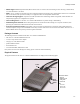
Modes Feature Functionality Power Ethernet Port Connect the supplied power adapter here. Connect the 10/100BaseT ethernet cable here. In AP mode or AP/Router mode, this is connected to the LAN or WAN. In Config mode, this is connected to the computer. In Client mode, this is connected to the computer. LEDs: • Power LED On - Power is available. • Wireless LED Off - No power. On - Wireless interface available. Off - Wireless interface unavailable. • Ethernet LED Flashing - Data being transferred.
Modes Access Point (AP) Mode Figure 2. Access Point Mode Configuration Access Point (AP) mode is used with existing secure home and corporate networks. In AP mode, the APC 3-in-1 Wireless Mobile Router connects wireless stations to each other, and to the LAN on the Ethernet port. Because the APC 3-in-1 Wireless Mobile Router is “transparent” (that is, it does not have an IP address) it cannot be configured in AP mode (use Config mode instead).
Modes Use AP/Router mode in any of the following situations: • The Ethernet port is connected to a broadband modem rather than an Ethernet port. • There is permission for ONLY ONE (1) user to connect to the LAN or WAN, but multiple user connections are required. (In AP/Router mode, the IP address on the Ethernet port is shared by all wireless clients.) Notes: 1.
Modes Use Client mode in any of the following situations: • The device does not have a wireless interface. • The device’s wireless interface does not support the required features. • Simultaneous connection to two (2) wireless networks is needed - one via the wireless interface, the other via the Ethernet port and the APC 3-in-1 Wireless Mobile Router.
Requirements Chapter 2: The Initial Configuration This chapter provides information about the initial configuration of the APC 3-in-1 Wireless Mobile Router, including the following: • Requirements • How to Perform the Initial Configuration • Using The System Setup Screen • Using The Config File Screen • Upgrading the Firmware Requirements The following are required to do the initial configuration: • Network cable. Use a standard 10/100BaseT network (UTP) cable with RJ45 connectors.
How to Perform the Initial Configuration 6. By default, the admin username is Admin and password is APC. If the admin password has been set (on the System screen), a prompt appears for the username and password. Enter admin for the user name, and enter the current password. The Mode Configuration screen appears. Figure 5. The Mode Configuration Screen The Mode Configuration screen provides access to the three main setup screens: • AP mode - settings for AP (Access Point) mode.
Using The System Setup Screen Using The System Setup Screen Use the System Setup screen to enter settings that are mode-independent. Figure 6. The System Setup Screen The following table describes the fields in the System Setup screen. Admin Administrator PC Mac Address This is used to identify the computer. Provide this information if this computer is normally used. If the computer has both a 10/100BaseT Ethernet port, and a Wireless interface, then it will have a different MAC address for each.
Using The Config File Screen System Device Name Firmware version The name of the APC 3-in-1 Wireless Mobile Router. This field can be modified as needed. Displays the current version of the firmware. Click the Upgrade Firmware button to install a new version of the firmware (the new firmware file must be downloaded first). Config File Clicking the button will display the Upgrade Firmware screen. See the following section for further details.
Upgrading the Firmware Upgrading the Firmware The firmware (software) in the APC 3-in-1 Wireless Mobile Router can be upgraded using the Web browser. To do this: 1. Download the upgrade file. 2.Select Upgrade on the System Setup screen. A screen similar to the following appears. Figure 8. The Upgrade Firmware Screen Use these steps to upgrade the firmware: 1. Click the Browse button and navigate to the location of the upgrade file. 2. Select the upgrade file.
Upgrading the Firmware 2-6
Connecting the Router to a Wired or Wireless Network Chapter 3: Configuring the Router for Access Point (AP) Mode This chapter provides setup information for the Access Point (AP) mode of the APC 3-in-1 Wireless Mobile Router including: • Connecting the Router to a Wired or Wireless Network • Using the Wireless Security Screen • Using the Trusted Wireless Stations Screen It is not possible to connect to the APC 3-in-1 Wireless Mobile Router while it is in this mode.
Using the Wireless Security Screen The following table describes the fields on the AP Mode Setup Screen. Wireless Region SSID Select the region where the computer is located. If using an ESS (Extended Service Set, with multiple access points) this ID is called an ESSID (Extended Service Set Identifier). It is possible to change the SSID to a preferred value. Broadcast SSID AP mode and AP/Router mode must use different SSIDs. Using the same SSID for both modes would confuse wireless clients.
Using the Wireless Security Screen The Wireless Security (WEP) Screen The Wireless Security screen displays when WEP is selected. Figure 10. The Wireless Security Screen (AP Mode - WEP) The following table describes the fields on the WEP Wireless Security screen. Security System Select the desired option: • Disabled • WEP • WPA-PSK Authentication Key Size The screen will change according to the current selection. The following settings are visible only if WEP is selected.
Using the Trusted Wireless Stations Screen The Wireless Security (WPA-PSK) Screen The following image shows the Wireless Security screen when WPA-PSK is selected. Figure 11. The Wireless Security Screen (WPA-PSK) The following table describes the fields on the Wireless Security (WPA-PSK) screen. Security System Select the desired option: • Disabled • WEP • WPA-PSK PSK Key Lifetime Encryption The screen will change according to the current selection.
Using the Trusted Wireless Stations Screen Edit To change an existing entry in the Trusted Stations list: 1. Select the Station in the Trusted Stations list. 2. Click the Edit button. The address will be copied to the Address field, and the Add button will change to Update. 3. Edit the address (MAC or physical address) as required. Add Clear 4. Click Update to save any changes. To add a Trusted Station which is not in the Other Wireless Stations list, enter the required data and click this button.
Using the Trusted Wireless Stations Screen 3-6
Connecting in AP/Router Mode Chapter 4: Configuring the Router for AP/Router Mode This chapter provides setup information for the AP/Router mode of the APC 3-in-1 Wireless Mobile Router. In AP/Router mode, the router provides the following services: • Wireless Access Point • DHCP Server • Shared IP address • Firewall Protection for Wireless stations. To configure the router in AP/Router mode, connect while in Config mode or in AP/Router mode.
Using the AP/Router Setup Screen Using the AP/Router Setup Screen This screen displays after clicking the Config button for AP/Router mode on the Mode Configuration screen. Figure 13. The AP/Router Setup Screen The following table describes the fields on the AP/Router Setup screen. Wireless SSID If using an ESS (Extended Service Set, with multiple access points) this ID is called an ESSID (Extended Service Set Identifier). It is possible to change the SSID to a preferred value.
Using the AP/Router Setup Screen Allow trusted stations only This feature can be used to prevent unknown Wireless stations from using this access point. To use this feature: 1. Enable this checkbox. 2. Click the Trusted Stations button to open a sub-window containing the Trusted Wireless Stations screen. 3. Enter details of the Trusted Wireless Stations. See the following section for further details.
The Wireless Security Screen The Wireless Security Screen The Wireless Security screen displays after clicking the Wireless Security button on the AP/Router Setup screen. The default security setting is Disabled. No configuration is required. Data is not encrypted before transmission.
The Wireless Security Screen Security System: WPA-PSK When WPA-PSK is selected on the Wireless Security screen, the following screen displays. Figure 15. The Wireless Security Screen (WPA-PSK) The following table describes the fields on the WPA-PSK Wireless Security screen. Security System Select the desired option: • Disabled • WEP • WPA-PSK PSK Key Lifetime Encryption The screen will change according to the current selection. The following settings are only visible if WPA-PSK is selected.
The Trusted Wireless Stations Screen The Trusted Wireless Stations Screen The Trusted Wireless Stations screen displays after clicking the Trusted Stations button on the AP/Router Setup screen. Figure 16. The Trusted Wireless Stations Screen (AP/Router Mode) The following table describes the fields on the Trusted Wireless Stations screen. Trusted Wireless Stations Other Wireless Stations Address This lists any Wireless stations which are designated as Trusted.
The Ethernet (WAN) Port Configuration Screen The Ethernet (WAN) Port Configuration Screen By default, the APC 3-in-1 Wireless Mobile Router will try to obtain an IP address automatically on the Ethernet (WAN) port. If this does not work in the current environment, click the Configure button to change the settings for the Ethernet (WAN) port.
The Ethernet (WAN) Port Configuration Screen MAC Address MAC Address Also called Network Adapter Address or Physical Address. This is a low-level network identifier, as seen from the WAN port. Normally there is no need to change this field, but if necessary, use the Copy from PC button to copy the computer's address into this field. This is only necessary if the computer’s MAC address has been recorded. Use the Default button to insert the default value, or enter a value directly, if desired.
The Ethernet (WAN) Port Configuration Screen To determine which method to use, contact the System Administrator. The following screen shows all the available settings. Figure 18. Ethernet Port Configuration (All Settings) The following table describes all possible fields on the Ethernet Port Configuration screen. Connection Type Connection Type The available options are: Travel Mode (Hotel) - This is the default. No data needs to be input. This setting will work in many situations, not just hotels.
The Ethernet (WAN) Port Configuration Screen IP Address IP Address is assigned automatically Specified IP Address Also called Dynamic IP Address. This is the default, and the most common. Only change this if advised to do so by the person or organization providing the LAN/WAN port connection. Also called a Static IP Address. If this option is selected, the following data must be entered. • IP Address - The IP address on the LAN or WAN. • Network Mask - The subnet mask associated with the IP address above.
The Ethernet (WAN) Port Status The Ethernet (WAN) Port Status To check the status of the Ethernet (WAN) port connection, click the Status button on the AP/Router Setup screen. This opens a window and the screen that displays depends upon the connection method currently in use.
The Ethernet (WAN) Port Status Buttons This button is only useful if the IP address shown above is allocated automatically on connection. (Dynamic IP address). This button is not used with a Fixed (Static) IP address. Release/Renew Button will display EITHER Release OR Renew If the ISP's DHCP server has NOT allocated an IP address for the APC 3-in-1 Wireless Mobile Router, this button reads Renew.
The Ethernet (WAN) Port Status Connection Log The Connection Log shows status messages relating to the existing connection. The most common messages are listed in the section “The following table describes the Connection Log Messages..” The Clear Log button will restart the log, while the Refresh button will update the messages shown on screen. Buttons Clear Log Connect Disconnect Refresh Deletes all data currently in the log, making it easier to read new messages.
The Ethernet (WAN) Port Status Connection Status - PPTP (Point-to-Point Tunneling Protocol) Screen If using PPTP (Point-to-Point Tunneling Protocol), a screen similar to the following is displayed when the Status button is clicked. Figure 21. The PPTP Status Screen The following table describes the fields on the PPTP Screen. Connection Physical Address IP Address PPTP Status The hardware address of this device, as seen by remote devices on the Internet.
The Ethernet (WAN) Port Status Connection Status - L2TP Screen If using L2TP, a screen similar to the following is displayed when the Status button is clicked. Figure 22. The L2TP Status Screen The following table describes the fields on the L2TP Screen. Connection Physical Address IP Address Connection Status The hardware address of this device, as seen by remote devices on the Internet. (This is different from the hardware address seen by devices on the local LAN.
The Ethernet (WAN) Port Status 4-16
The Advanced Internet Screen Chapter 5: AP/Router Mode - Advanced Features This chapter explains when and how to use the advanced features in AP/Router mode.of the APC 3-in-1 Wireless Mobile Router. The following advanced features are provided in AP/Router mode.
The Advanced Internet Screen Send Application’s incoming calls to: Lists the computers on the Wireless LAN. For each application listed above, choose a destination computer. If necessary, add devices manually, using the PC Database menu option. There is no need to press Save after each change; simply set the destination computer for each application, then click Save. DMZ Enable DMZ using... Enables the DMZ feature as required. The DMZ PC will receive all “Unknown” connections and data.
The Advanced Internet Screen APC 3-in-1 Mobile Wireless Router Figure 24. Port Forwarding IP Address Seen by Internet Users To Internet users, all virtual servers on the LAN have the same IP address. This IP address is allocated by the ISP. This address should be static, rather than dynamic, to make it easier for Internet users to connect. If desired, use the DDNS (Dynamic DNS) feature to allow users to connect to Port Forwarding using a URL instead of an IP address.
The Port Forwarding Screen The Port Forwarding Screen The Port Forwarding screen is reached by the Port Forwarding link. The following is a sample screen. Figure 25. The Port Forwarding Screen This screen lists a number of pre-defined servers and allows users to define their own servers. Details of the selected server are shown in the Properties area. The following table describes the fields on the Port Forwarding Screen. Service Service Lists a number of pre-defined and user-defined services.
Using Self-defined Servers Update Selected Server Add as new Server Updates the current entry, using the data shown in the Properties area on screen. Adds a new entry to the list, using the data shown in the Properties area on screen. The entry selected in the list is ignored, and has no effect. Note: For each entry, the computer must be running the appropriate server software.
Using Dynamic DNS (Domain Name Server) Using Dynamic DNS (Domain Name Server) This free service is very useful when combined with the Port Forwarding feature. It allows Internet users to connect to user-defined servers using a URL, rather than an IP address. This also solves the problem of having a dynamic IP address, since these change whenever a connection is made. The service works as follows: 1. Register for the service at one of the listed DDNS service providers. 2.
Using Dynamic DNS (Domain Name Server) The following table describes the fields on the Dynamic DNS Screen. DDNS Service DDNS Service Select the desired DDNS service provider from the list. Register for the service at one of the listed service providers. Users can access the service provider's Web site by selecting it in the list and clicking the Web Site button. Apply for a domain name, and ensure it is allocated.
The Network Diagnostics Screen The Network Diagnostics Screen Use this screen to perform a Ping or a DNS lookup. These activities can be useful in solving network problems. Figure 27. The Network Diagnostics Screen The following table describes the fields on the Network Diagnostics screen. Ping Ping this IP Address Ping Button Enter the IP address to ping. The IP address can be on the LAN or on the Internet.
The Options Screen The Options Screen This screen allows advanced users to enter or change settings. For normal operation, there is no need to use this screen or change any settings. Figure 28. The Options Screen The following table describes the fields on the Options Screen. Backup DNS Backup DNS IP Address Enter the IP address of the DNS (Domain Name Servers) here. These DNS’ will be used only if the primary DNS is unavailable.
The Advanced PC Database Screen The Advanced PC Database Screen This screen displays when the Advanced button on the PC Database screen is clicked. It provides more control than the standard PC Database screen. Use this screen to select a computer (such as for the DMZ PC). It eliminates the need to enter IP addresses and use fixed IP addresses on the wireless LAN. Figure 29. The Advanced PC Database Screen Computers that are DHCP clients are automatically added to the database, and updated as required.
The Advanced PC Database Screen The following table describes the fields on the Advanced PC Database Screen. Known PCs Lists all current entries. The data displayed is the name, IP address, and type. The “type” indicates whether the computer is connected to the LAN. PC Properties Name IP Address If adding a new computer to the list, enter its name here. This entry should match the computer's hostname. Enter the IP address of the computer.
The Security Screen The Security Screen Use this screen to set firewall and other security-related options. Figure 31. The Security Screen The following table describes the fields on the Security Screen. Firewall Enable DoS Firewall If enabled, DoS (Denial of Service) attacks will be detected and blocked. The default is enabled. It is strongly recommended that this setting be left enabled.
The Security Screen Allow PPTP PPTP (Point-to-Point Tunneling Protocol) is widely used by VPN (Virtual Private Networking) programs. If checked, PPTP connections from the Wireless LAN are allowed. Allow L2TP If not checked, PPTP connections are blocked. L2TP is a protocol developed by Cisco for VPNs (Virtual Private Networks). If checked, L2TP connections from the Wireless LAN are allowed. If not checked, L2TP connections are blocked.
The Security Screen 5-14
Connecting the Computer to the Router Chapter 6: Configuring the Router for Client Mode This chapter describes how to configure the APC 3-in 1 Wireless Mobile Router for Client mode. Note: It is not possible to connect to the APC 3-in-1 Wireless Mobile Router while it is in Client mode. Configuration for Client mode must be performed while in Config mode.
The Client Mode Setup Screen The Client Mode Setup Screen Figure 32. The Client Mode Setup Screen The following table describes the fields on the Client Mode Setup screen. Wireless Profiles All available profiles are listed. For each profile, the following data is displayed: * If an * is displayed before the name of the profile, this indicates the profile is the current profile (it is enabled). Profile Name - The current profile name is displayed. [SSID] - The current SSID associated with this profile.
The Wireless Client Profile Screen The Wireless Client Profile Screen This screen displays when the Add or Edit button on the Client Mode Setup screen is clicked. Figure 33. The Wireless Client Profile Screen The following table describes the fields on the Wireless Client Profile screen. General Profile Name Network Type Enter a unique name for this profile.
The Wireless Client Profile Screen Security Security Sytem Select the desired option and then enter the settings for the selected method: Disabled - No security is used. Data is not encrypted before transmission. WEP - The 802.11b standard. Data is encrypted before transmission. Threre are 2 options: • WEP 64 Bit uses 64-bit encryption. Users must enter the WEP kep (10 Hex characters). • WEP 128 Bit uses 128-bit encryption. Users must enter the WEP key (26 Hex characters).
When Changing Modes Chapter 7: Operation and Usage This chapter provides information on what to consider when changing modes on the APC 3-in-1 Wireless Mobile Router and the status screens: • When Changing Modes • Using AP Mode • Using AP/Router Mode • Using Client Mode The mode can be changed ONLY by using the mode selector switch on the side of the APC 3-in-1 Wireless Mobile Router.
Using AP/Router Mode Using AP/Router Mode 1. Use a standard LAN cable to connect the Ethernet port to the desired LAN or WAN. Note: To avoid potential problems, do not change the LAN/WAN connection from the APC 3-in-1 Wireless Mobile Router to the computer, or vice versa. Doing so may cause the connection to fail. 2. Use the mode selector switch on the side on the APC 3-in-1 Wireless Mobile Router to select AP/Router mode. 3. Wait for the restart to complete and for the Ethernet LED to turn on. 4.
Using AP/Router Mode Figure 34. The AP/Router Setup Screen (annotated) 4. Check the Ethernet (WAN) port status and settings. If the APC 3-in-1 Wireless Mobile Router has not obtained a valid IP address — click the Configure button and change the settings as required. Check with the LAN administrator, if necessary, to determine the correct settings. If the LAN/WAN is using the same IP address range as the Wireless LAN — change the wireless LAN AP/Router IP address to use a different address range.
Using Client Mode Using Client Mode In Client mode, the Ethernet port of the APC 3-in-1 Wireless Mobile Router must be connected to the Ethernet port of the computer. Before using Client mode, ensure that the Client mode configuration is correct. Configuration must be performed in Config mode. (Admin connections are not possible while in Client mode.) See Chapter 6, “Configuring the Router for Client Mode” for information about Client mode setup.
Appendix A: Troubleshooting and Maintenance This appendix covers the following common problems that may be encountered while using the APC 3-in-1 Wireless Mobile Router and some possible solutions to them: • General Problems • Wireless Access — AP or AP/Router Mode • Router Mode If problems still exist after performing these procedures, contact the dealer. General Problems Problem 1: Cannot connect to the APC 3-in-1 Wireless Mobile Router to configure it.
Problem 3: The wireless connections speed is very slow. Solution: The wireless system will connect at the highest possible speed, depending on the distance and the environment. To obtain the highest possible connection speed, experiment with the following: • Location of the APC 3-in1 Wireless Mobile Router Try adjusting the location and orientation of the APC 3-in-1 Wireless Mobile Router. • Wireless Channel If interference is the problem, changing to another channel may show a marked improvement.
Appendix B: About Wireless LANs This appendix provides some background information about using wireless LANs (WLANs) and describes the following: • Modes for Wireless LANs • Basic Service Set (BSS) and Extended Service Set (ESS) • Wired Equivalent Privacy (WEP) Modes for Wireless LANs Wireless LANs can work in either of two modes: • Ad hoc Mode • Infrastructure Mode Ad hoc Mode Ad hoc mode does not require an access point or a Wired (Ethernet) LAN.
will still scan all channels to see if there is an existing ad hoc group they can join. Wired Equivalent Privacy (WEP) WEP (Wired Equivalent Privacy) is a standard for encrypting data before it is transmitted. This function is desirable because it is impossible to secure any data that is transmitted by wireless stations. However, if the data is encrypted, then it is meaningless unless the receiver can decrypt it.
Appendix C: Specifications This appendix provides the following information: • Multi-Function APC 3-in-1 Wireless Mobile Router Specifications • Wireless Interface Specifications • Regulatory Approvals • Warranty • Technical Support Multi-Function APC 3-in-1 Wireless Mobile Router Specifications Model Dimensions Operating Temperature Storage Temperature Network Protocol Network Interface LEDs Power Adapter APC 3-in-1 Wireless Mobile Router 70 mm (W) * 105 mm(D) * 22 mm (H) 0° C to 40° C (32° F to 104° F)
Warranty The standard warranty is two (2) years from the date of purchase. APC’s standard procedure is to replace the original unit with a factory reconditioned unit. APC will ship the replacement unit once the defective unit has been received by the repair department, or cross-ship upon the receipt of a valid credit card number. The customer pays for shipping the unit to APC. APC pays ground freight transportation costs to ship the replacement unit to the customer.