
Installation Guide
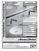


TOOLS REQUIRED; Fig. 2
Fig. 2
1 Slip Jaw Pliers
2 Adjustable Wrench
3 Plumbers' Putty or Caulking
4 Phillips Screwdriver
5 Flat Blade Screwdriver
6 Electric Drill & 1/4" Drill Bit
7 Tape Measure
1
2
3
4
5
6
7
10'
2
M965653 Rev. 1.4 (10/15)
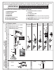
Fig. 1
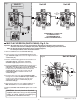
Roughing-in Dimensions
114mm
(4-1/2)
500mm
(20)
381mm
(15)
3/8" COMP.
32mm (1-1/4)
55.5mm
(2-3/16)
125mm
(4-7/8)
81mm
(3-3/16)
49mm
(2)
159mm
(6-1/4)
126mm
(5)
154mm
(6-1/16)
FINISHED
WALL
Fig. 1a
1
4
5
3
2
INSTALLATION
3
Fig. 1
SENSOR
CABLES
1
SEE DETAIL “A”
GENERAL DESCRIPTION:
Electronic faucet with proximity operation. Vandal resistant
solid brass construction single post mounting. Operates on
DC (battery/power pack) or AC permanent power
(plug-in/hardwire). In-line strainer for solenoid is integral.
Single inlet 3/8 compression, built-in check valves, and
flexible stainless steel 16-1/4" reach inlet hose for spout
connection.
Note: All plumbing and electrical wiring must be
installed in accordance with applicable codes,
regulations and standards.
CAUTION: Use only American Standard
supplied cable sets. Using non-AS supplied
cables, or cutting, splicing or modifying any
components will void the warranty.
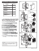
RECOMENDED ELECTRICAL BOX OR
EQUIVALENT BY OTHERS
HARD-WIRED AND MULTI AC 10’ MAX. CABLE LENGTH
4" (102mm) SQ. X 3-1/2" (89mm) DEEP ELECTRICAL BOX
Hubbel-RACO #256 OR EQUAL (BY OTHERS).
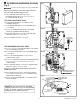
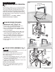
SPOUT ASSEMBLY INSTALLATION;
Fig. 1
CAUTION
Turn off hot and cold water supplies before beginning
1
1. Connect the two 27" EXTENSION CABLES (1) to
the Faucet Sensor Cables.
2. Insert 27" EXTENSION CABLES (1), FLEX HOSE
(2) and SPOUT SHANK (3) through center hole of
mounting surface.
3. Assemble "C" WASHER (4) and LOCKNUT (5)
onto SPOUT SHANK (3) from underside of
mounting surface.
4. Align FAUCET and tighten LOCKNUT (5).
Note: 4" and 8" Deck Plates are available for other
installations, see page one for information.