
Installation Guide
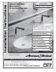


M965653 Rev. 1.4 (10/15)
5
CAUTION: Use only American Standard
supplied cable sets. Using non-AS supplied
cables, or cutting, splicing or modifying any
components will void the warranty.
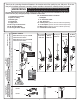
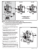
AC VERSIONS (HARDWIRE / PLUG-IN);
Fig. 2
B
CAUTION
Disconnect AC power supply before opening CONTROL BOX.
NOTE: For AC installation, make power supply connection
before mounting CONTROL BOX (3) to wall.
1. Remove CONTROL BOX COVER (1). Feed the
EXTENSION CABLES (2) from the Faucet through the
top of CONTROL BOX (3). Fig. 2.
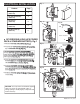
2a. Insert POWER CORD (8) through POWER SUPPLY
GROMMET (9) Fig. 2a.
3a. Insert POWER CORD (8) through side GROMMET (6) as
shown. Fig. 2a.
4a. Connect 27" EXTENSION CABLES (2) to SOLENOID
CABLE (7) and POWER CORD (8). Fig. 2a.
5a. Mount CONTROL BOX to wall. Replace CONTROL BOX
COVER (1). Tighten cover screws firmly.
6a. Plug AC POWER SUPPLY into wall outlet.
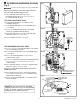
2b. Insert one end of the 10' EXTENSION (10a) through POWER
SUPPLY GROMMET (9). Fig. 2b.
3b. Insert 10' EXTENSION (10a) through side GROMMET (6) as
shown. Fig. 2b.
4b. Connect 10' EXTENSION (10a) to single terminal of
Y-ADAPTER (11). Fig. 2b.
5b. Connect 27" EXTENSION CABLES (2) to SOLENOID CABLE (7)
and to either of the two terminals at the one end of the
Y-ADAPTER (11).
6b. Mount CONTROL BOX (3) to wall. Replace CONTROL BOX
COVER (1). Tighten cover screws firmly.
Contractor to supply ELECTRICAL BOX (12) and power to
POWER SUPPLY (13).
7b. Mount POWER SUPPLY (13) into ELECTRICAL BOX (12).
Connect White and Black connections to POWER SUPPLY
CONNECTIONS (14). Fig. 2c.
8b. Connect the10' EXTENSION (10b) to the POWER SUPPLY
CABLE (15). Fig. 2c.
Fig. 2
Fig. 2a
10a
11
7
2
2
7
Fig. 2b
2
3
1
6
6
9
9
FROM ELECTRICAL BOX
WITH POWER SUPPLY
Fig. 2c
BLACK & WHITE
POWER
CONNECTIONS
15
13
CONNECTOR NOT
USED IN THIS
INSTALLATION
10b
14
4" ELECTRICAL BOX
OR EQUIVALENT BY
OTHERS
12
FOR HARDWIRE HOOK-UP ONLY;
8
2
PLUG INTO
WALL OUTLET
FOR PLUG-IN HOOKUP ONLY