
Installation Instructions


6
M965653 Rev. 1.8 (12/17)
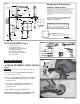
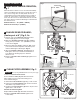
MULTI-AC VERSION (DAISY-CHAIN); Fig. 3, 3a
Important: All control box covers must be removed before beginning to make daisy-chain connections.
Disconnect the first unit’s Y-Adapter from power supply before making daisy-chain connections.
Note: For Unit #1 electrical instructions, refer to section B (page 5).
For subsequent Units, refer to instructions below...
C
Unit #2 Detail
Fig. 3a
CAUTION: Use only American Standard
supplied cable sets. Using non-AS supplied
cables, or cutting, splicing or modifying any
components will void the warranty.
5
5b
10b
6a
6b
10a
7
2
2
11
11a
3
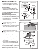
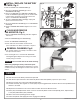
1. Remove COVERS from all CONTROL BOX (3).
2. Insert pervious unit’s 10' EXTENSION (11a) through
gray GROMMET (5b) and connect to single terminal of
Y-ADAPTER (11).
3. Remove solid black plug grommet from left side of all
CONTROL BOX (3), and replace with GRAY
GROMMET (5b). (Supplied with each Faucet).
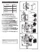
4. Feed 27" EXTENSION CABLES (2) through the top of
CONTROL BOX (3). Connect one 27" EXTENSION
CABLE (2) to the SOLENOID CABLE (7), and the other
to either of the two terminals at the one end of the
Y-ADAPTER (11). Connect the current unit’s 10'
EXTENSION (10a) to available terminal of the
Y-ADAPTER (11).
5. Feed the other end of the 10 ft.EXTENSION (10b)
through the two GRAY GROMMETS (6a and 6b) and
connect to the single terminal of the next unit’s
Y-ADAPTER (11). Place Y-ADAPTER (11) into
CONTROL BOX (3).
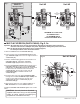
6. Repeat Steps above for each additional Unit, for a
Max. of 15 Units on one AC POWER SUPPLY.
7. Replace CONTROL BOX COVERS. Tighten cover screws
firmly.
Unit #2 Unit #3
Fig. 3
10 ft.
EXTENSION
CABLE
AC POWER
SUPPLY
*MAXIMUM OF 15 UNITS PER
AC POWER SUPPLY.
10' MAXIMUM CABLE
LENGTH BETWEEN UNITS.
OR
Unit #1
Already installed
BLACK &
WHITE
POWER
CONNECTIONS