
Installation Guide

2
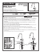
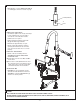
INSTALL CONTROL BOX
M965857 (11/17)
3
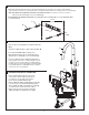
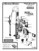
CONNECT SPRAY HOSE AND BOX, INSTALL WEIGHT
C
H
A
D
C
B
E
F
G
A
B
E
F
G
D
C
1
3
2
4
7
6
- 2 -
• Push the Wire Assembly (E, F) into FEMALE ADAPTER
(E, F).
• Thread Hose (A, B, C, D) onto Male adapter (A, B, C, D).
• Push WIRE ASSEMBLY (G) into Battery Pack.
• With HAND SPRAY (1) seated in SPOUT (2), install
WEIGHT (3) onto HOSE (A), secure with SCREW (4).
• Connect FLEXIBLE SUPPLY HOSES (H, C) directly to
water supplies. Connection on tting supplies are 3/8”
compression. Connect left supply hose (Red Stripe) to
Hot wall supply. Connect right supply hose (Blue Stripe)
to Cold wall supply. Use adjustable wrench to tighten
connections. Do not over tighten.
• Determine desired height and location (optional) and mark the top center line. Use a level to help mark the
vertical center line for the two mounting locations. The distance between the two mounting holes is 2-3/8" (60 mm).
Note: This dimension is important and must be maintained. If BOX is secured to a stud or cross brace
with in the wall, drill small pilot holes for SCREWS (2).
• For installations on drywall or tiled walls: Use ANCHORS (1) and SCREWS (2) for securing CONTROL BOX
to the nished wall.
LEVEL
1
2
C/L
2-3/8"
(60 mm)
3a
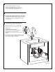
SECURING ELECTRICAL CONNECTION
• Attach CABLE MOUNTS (5) along the inside
of the kitchen cabinet walls positioning them
accordingly as shown. Wipe clean surfaces
before attaching CABLE MOUNTS (5).
• Attach ‘HOOK TO LOOP’ FASTENER (black strip) (6)
to the back side of the BATTERY HOLDER (7) and
attach ‘HOOK TO LOOP’ FASTENER (black strip) (6)
on desired location inside the kitchen cabinet.
Wipe mounting surface clean before attaching
‘HOOK TO LOOP’ FASTENER (black strip) (6).