
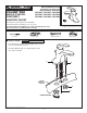
Installation Guide

- 2 -
2
3
4
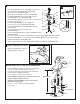
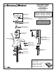
• Operate LIFT KNOB (1) to verify that
STOPPER (2) opens and closes.
CHECK OPERATION OF POP-UP
MAKE WATER SUPPLY AND WASTE CONNECTIONS
M965766 (8/16)
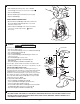
• Push TAIL PIECE (11) down into TRAP (C) (threaded end up).
• Thread LOCKNUT (5), WASHER (4) and GASKET (3)
(Bevel side up) onto DRAIN BODY (10).
• Apply a bead of PUTTY (D) to underside of FLANGE (2).
• Feed DRAIN BODY (10) up through SINK (A) and thread
the FLANGE (2) fully onto DRAIN BODY (10).
• Tighten LOCKNUT (5) rmly, keeping the pivot rod hole pointed
towards the back of the sink.
• Assemble PIVOT ROD (9) as shown in Figure-2a.
Notice the position of the CONCAVE WASHER (G).
• Insert PIVOT ROD (9) into DRAIN BODY (10) and tighten
PIVOT NUT (F).
• Pull TAIL PIECE (11) up and thread tightly into
DRAIN BODY (10).
• Position EXTENSION ROD (7) onto POP-UP ROD (E) and tighten
THUMBSCREW (6).
• Remove one end of CLIP (8) from PIVOT ROD (9) by squeezing ENDS TOGETHER WHILE SLIDING.
• Insert PIVOT ROD (9) into second or third hole in EXTENSION ROD (7) and reassemble CLIP (8).
• DROP STOPPER (1) into DRAIN BODY (10).
• Adjust stopper height by repositioning EXTENSION ROD (7) and tightening THUMBSCREW (6).
INSTALL POP-UP DRAIN
1
APPROX. 20"
2
COLD
HOT
3/8" COMPRESSION
RED
BAND
BLUE
BAND
• Connect FLEXIBLE SUPPLIES (1, 2) directly to wall supplies.
Connection on tting supplies are 3/8" compression.
Connect left SUPPLY (1) to Hot (Marked with a Red Band)
and right supply to COLD (2) wall supply.
• Faucet supplies are 20" long from faucet base.
Note: If additional supply length is required, installer must
purchase additional parts separately.
Important: If SUPPLY HOSES (1, 2) are to long, loop as
illustrated to avoid kinking.
• Connect 1-1/4” O.D. tailpiece on POP-UP DRAIN to
waste outlet.
1-1/4"
6
E
D
7
8
9
C
F
2
A
1
3
4
5
10
11
2a
F
G
2
1