
Installation Guide

9
2
4
5/16'' MIN.
MOUNTING
SURFACE
10
11
11
10
1
3
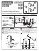
Push TUBING (3) ends into VALVE (4) side outlets. Insert VALVES (4)
into mounting holes from underside of ledge.
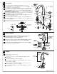
Press TEE (5) onto SPOUT SHANK (6) making certain that the O-RING (7) is
properly seated on SHANK (6). Push COUPLING (8) into TEE (5) and attach to
SPOUT SHANK (6) and tighten using a 10mm (3/8'') hex wrench. Tighten
COUPLING (8) using a 10mm (3/8") Hex wrench. (FOR 7020.900/920) Use
COUPLING (8a) for fitting less spray.
Install LOCKNUTS (1) and RUBBER WASHERS (2) onto valve shanks.
Place RUBBER RING (10) into ESCUTCHEON ADAPTERS (9) and thread onto
valves until snug against internal stop.
Tighten LOCKNUT (1) with WRENCH supplied to secure VALVE (4) position.
Slide FERRULE (12) and COUPLING NUT (13) to outlet of VALVE (4) and tighten
COUPLING NUT (13) firmly.
Connect HOT water supply to inlet of left VALVE and COLD water supply to inlet of
right VALVE using appropriate connector.
VALVE ASSEMBLY
HOT
COLD
12
4
13
7
6
8
8a
5
13
12
3
4
MOUNTING
SURFACE
Thread of VALVE BODY (4) should extend at least 5/16 inch above MOUNTING
SURFACE (11). If necessary, adjust LOCKNUT (1).
10
9
9
M 9 6 5 0 2 7 R E V. 1.6
Wrench
4
INSTALL HANDLES
SERVICE
5
2
90˚
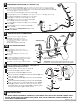
To change direction of handle rotation,
proceed as follows:
Turn valve to OFF position. Unthread HANDLE BASE (1) from DECK
ADAPTER (2).
Pull HANDLE ASSEMBLY off VALVE STEM (3).
Remove SPRING CLIP (4). Lift STOP WASHER (5), turn 90˚ and replace.
Replace SPRING CLIP (4).
Find correct position of HANDLE ASSEMBLY by adjusting male teeth on
VALVE STEM (3) to female teeth in HANDLE.
Thread HANDLE ASSEMBLY onto DECK ADAPTER (2) until snug against
mounting surface.
4
3
5
HANDLE
ASSEMBLY
REMOVE
HANDLE
1
2
4
5
3
BOTTOM
SPLINE
END UP
Push ADAPTER (1) on VALVE STEM (2), so that the hole of the
ADAPTER (1) with the spline is facing up. Fig. A. Tighten
STEM SCREW (3) to secure ADAPTER (1).
Find correct position of LEVER HANDLE ASSEMBLY (4) by adjusting
male teeth on ADAPTER (1) to female teeth in HANDLE (4).
Thread LEVER HANDLE ASSEMBLY (4) onto DECK ADAPTER (5)
until snug against mounting surface.
THREAD ON
TO DECK
ADAPTER
Fig. A.