
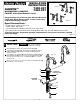
Installation Instructions

2
1
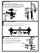
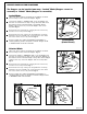
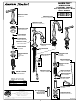
VALVE OUTLET SUPPLY CONNECTION
3
RED BAND
BLUE
BAND
Connect Red Banded Hose to Left Valve and Blue Banded Hose to Right Valve.
Attach COUPLING NUTS (1) of SUPPLY HOSES (2) and tighten making water tight connections.
Important: Loop SUPPLY HOSES (2) as illustrated so they do not kink.
COLD
HOT
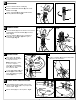
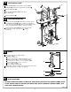
VALVE INSTALLATION
M965238
MOUNTING
SURFACE
Install LOCKNUT (3) and RUBBER WASHER (4) onto VALVE BODY (5).
From under side of mounting surface, install VALVE BODY (5) through valve
mounting hole. Threads of VALVE BODY (5) should extent at least 5/16
of a inch above mounting surface top. Fig. A. Thread DECK ADAPTER (2)
onto VALVE BODY (5) until snug against internal stop. If necessary, adjust
LOCKNUT (3). Tighten LOCKNUT (3) with WRENCH (6) supplied.
6
2
1
4
3
5
2
1
4
3
Place RUBBER RING (1) into DECK ADAPTER (2).
5
5
5/16'' MIN.
Fig. A.
2
4
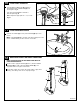
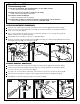
INSTALL HANDLES
1
2
5
3
TOP
Figure "A"
SPLINE
END UP
Push ADAPTER (1) on VALVE STEM (2). See Fig. A. Tighten
STEM SCREW (3) to secure ADAPTER (1).
Find correct position of LEVER HANDLE ASSEMBLY (4) by adjusting
male teeth on ADAPTER (1) to female teeth in HANDLE (4).
Thread LEVER HANDLE ASSEMBLY (4) onto DECK ADAPTER (5)
until snug against mounting surface
.
THREAD ON
TO DECK
ADAPTER
4