
Installation Guide

- 3 -
5
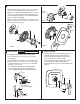
• By restricting HANDLE rotation and limiting the amount of hot water
allowed to mix with the cold, the HOT LIMIT SAFETY STOP (1)
reduces risk of accidental scalding. To set the maximum hot water
temperature of your faucet, all you need to do is adjust the setting on
the HOT LIMIT SAFETY STOP (1).
• T u r n CARTRIDGE STEM (2) to the OFF position (coldest setting) before
making adjustment to HOT LIMIT STOP (1). Use a at blade screwdriver
to pry free the HOT LIMIT SAFETY STOP (1). Pull forward and rotate
counterclockwise one number to limit hot water temperature.
Use ARROW (3) on CARTRIDGE (4) and NUMBERS (5) on HOT LIMIT
STOP (1) for indication.
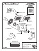
• Remove HANDLE (see step 3 and reverse).
• Remove ESCUTCHEON and CARTRIDGE CAP (see step 1 and re-
verse).Shut off water supply by either closing off main water supply, or
closing off the hot and cold CHECK STOPS on valve.
TO GAIN ACCESS TO VALVE FOR SERVICING
ADJUST HOT LIMIT STOP
4
M965724 Rev. 1.0 (7/16)
1
5
1
3
1
1
9
7
5
3
1
0
1
5
1
3
1
1
9
7
5
3
1
1
5
1
3
1
1
9
7
5
3
1
COLDER
(Larger Numbers)
0 1 3 5 7 9 11 13 15
HOTTER
(Smaller Numbers)
0 1 3 5 7 9 11 13 15
1
5
4
3
1
5
4
3
2
2
6
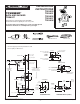
CARE INSTRUCTIONS:
DO: SIMPLY RINSE THE PRODUCT CLEAN WITH CLEAR WATER. DRY WITH A SOFT COTTON FLANNEL CLOTH.
DO NOT: DO NOT CLEAN THE PRODUCT WITH SOAPS, ACID, POLISH, ABRASIVES, HARSH CLEANERS, OR A
CLOTH WITH A COARSE SURFACE.
BACK TO BACK INSTALLATION
ROTATE 180˚
1
2
9
5
5
7
8
6
4
3
INLETS
LARGE OUTLET
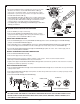
VALVE LEAKS WHEN SHUT OFF
• Remove CARTRIDGE (1) by removing CARTRIDGE SCREWS (2). Remove three SCREWS (3) from FIXATION RING (4)
and pull out PRESSURE BALANCING (5) unit.
• Clean SEALS (9) on base of CARTRIDGE (1). Check base of PRESSURE BALANCING UNIT (5) and clean O-RINGS (6).
Remove CAPS (7) and check O-RINGS on inside of CAPS (7). Clean inside sealing surfaces of VALVE BODY (8).
• Re-assemble PRESSURE BALANCING UNIT (5) and CARTRIDGE (1). Tighten all screws. Turn on water supply and see
above for installing TRIM and HANDLE.
UNABLE TO MAINTAIN CONSTANT TEMPERATURE
• Remove PRESSURE BALANCE UNIT (5).
• Remove CAPS (7) and clean valve thoroughly.
• Examine balancing unit and check condition of O-ring on end of piston. Piston should move back and forth.
Order Repair Part M952100-0070A if balancing unit is defective.
• Replace CAPS (7) and install PRESSURE BALANCE UNIT (5). Make sure inlets line up with two holes in bottom of casting.
Top ange should butt-up against top of casting.
BACK TO BACK INSTALLATION
• Remove PRESSURE BALANCE UNIT (5). Rotate PRESSURE BALANCE UNIT (5) 180˚ so that the inlets face up and the large
outlet port faces down.
• Push PRESSURE BALANCE UNIT (5) in casting make sure inlets line up with holes in bottom of casting. Top ange should
butt up against top of casting.
• Reassemble FIXATION RING (4) and CARTRIDGE (1).