Operation Maintenance Manual OM 751-1 Group: Applied Systems Part Number: OM 751 Date: November 2006 MicroTech II® Unit Ventilator Controls for AAF®-HermanNelson® Classroom Unit Ventilators DX Cooling OnlySoftware Model UV05 Used with AAF-HermanNelson Classroom Unit Ventilator Model AVV - Floor Mounted Model AHV - Ceiling Mounted Model AZV, AZU - Floor Mounted Self Contained Air Conditioner IMPORTANT Before unit commissioning, please read this publication in its entirety.
Introduction. . . . . . . . . . . . . . . . . . . . . . . . . . . . . . . . 3 Acronyms/Abbreviations . . . . . . . . . . . . . . . . . . . . . . . . . . . . . . . . . . 5 Getting Started . . . . . . . . . . . . . . . . . . . . . . . . . . . . . 7 Using the Keypad/Display . . . . . . . . . . . . . . . . . . . . . . . . . . . . . . . . . 7 Display Format . . . . . . . . . . . . . . . . . . . . . . . . . . . . . . . . . . . . . 7 Keypad Functions . . . . . . . . . . . . . . . . . . . . . . . . . . . . . . . .
Introduction Introduction This manual provides information on the MicroTech II® control system used in the AAF®HermanNelson® Unit Ventilator product line. It describes the MicroTech II components, input/ output configurations, field wiring options and requirements, and service procedures. For installation and general information on the MicroTech II Unit Ventilator Controller, refer to IM 747, MicroTech II Unit Ventilator Controller.
Introduction Table 4: Software program literature Description Air Source Heat Pump with Electric Heat (Software Model 00) Water Source Heat Pump with Electric Heat (Software Model 02) Water Source Heat Pump without Electric Heat (Software Model 03) DX Cooling with Electric Heat (Software Model 04) DX Cooling Only (Software Model 05) Electric Heat Only (Software Model 06) DX Cooling with Hydronic Heat - Valve Control (Software Model 07) DX Cooling with Hydronic Heat - F&BP Damper Control (Software Model 08)
Introduction Acronyms/Abbreviations The following table list acronyms and abbreviations that may or may not be used within this manual. Other abbreviations for keypad displays and parameters can be found in Table 8 on page 14 and Table 26 on page 47.
Introduction Description Occupied Cooling Setpoint Occupied Heating Setpoint Occupancy Override Input Occupancy Sensor Input Proportional Integral Parts Per Million Positive Temperature Coefficient Relative Humidity Space Humidity Setpoint Read Only Read Write Standby Cooling Setpoint Standby Heating Setpoint Thermal Expansion Valve Unoccupied Cooling Setpoint Unoccupied Heating Setpoint Unit Ventilator Unit Ventilator Controller UVC (Heat/Cool) Mode Output UVC State Output Wet Heat Valve Position Ventilat
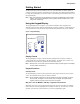
Getting Started Getting Started The MicroTech II Unit Vent Controller (UVC) is a self-contained device that is capable of complete, stand-alone operation. Information in the controller can be displayed and modified by using the keypad/display (local user interface). The following sections describe how to use the keypad/display. Note – Many UVC parameters are accessible both through the keypad/display and the network interface.
Getting Started Table 6: Keypad/display security levels Level 0 1 2 3 Display What is restricted? Password U0 Default level (access all) 10 Does not allow set point offset changes; U1 also locks out keypad/display menu 21 access. Does not allow set point offset changes nor MODE key changes; also locks out 32 U2 keypad/display menu access. Does not allow set point offset changes U3 nor MODE and FAN key changes; also 43 locks out keypad/display menu access.
Getting Started Using the Keypad/Display Viewing Actual Indoor Air Temperature (IAT) Normally, the effective set point temperature appears on the keypad/display. You also can use the keypad/display to view the indoor air temperature (IAT). See Figure 3. Note – When the actual indoor air temperature (Effective Space Temp Output) equals the effective set point temperature (Effective Set Point Output), you there is no change to the keypad/display when you view space temperature.
Getting Started Figure 5: Changing a keypad/display menu item Table 7: Keypad/display menu item list Display Keypad menu item list rA HC Reset Alarm Input UVC (Heat/Cool) Mode Output UVC State Output St d0 d1 d2 d3 SL Eo o( (o (S (U ko kS kU rS o1 o2 Discharge Air Temp Set point Output Discharge Air Temp Output Ventilation Cooling Low Limit set point Mechanical Cooling Low Limit set point Slave Type Configuration 05 RW x RO x RO x RO x DAT Display current DA temperature.
Getting Started RO RW1 05 RW x 99% RW x 12% RW x 99% RW x 0 RW x 35.6°F (2°C) Set economizer status: 0 = disable, 1 = enable. RW x 1 Adjust economizer OA temperature set point. DO NOT lower this set point below CCLO or you risk creating a deadband where no cooling occurs. RW x 68°F (20°C) ETD Adjust economizer IA/OA temperature differential. RW x 1.8°F (1°C) EES Adjust economizer OA enthalpy set point. RW x EED Adjust economizer IA/OA enthalpy differential.
Description of Operation Description of Operation State Programming The MicroTech II UVC takes advantage of “state” machine programming to define and control unit ventilator operation. “State” defines specific states or modes of operation for each process within the unit ventilator (e.g., heating, cooling, etc.) and contain the specific logic for each state.
Description of Operation Figure 6: Complete UVC—state diagram Off NightPurge 9 8 EmergencyHeat ModeSuperState FullHeat 7 FanOnly A CantHeat D AutoMode HeatMode SuperState CantHeat B CoolMode SuperState Heat Econ 5 3 LowLimit E CantCool C EconMech 1 DAHeat 4 LowLimit F Mech 2 UVC Unit Modes The UVC provides several “normal” modes of unit operation. These include: Off, Night Purge, Fan Only, Cool, Emergency Heat, Auto, Heat, and Cool.
Description of Operation Table 8: UVC state names and numbers Normal UVC modes State names OFF Night purge Fan only OFF Night Purge Fan Only Full Heat Cant Heat Heat Cant Heat Low Limit EconMech Mech Econ DA Heat Cant Cool Low Limit Emergency heat Heat Auto Cool State numbers Decimal 9 8 10 7 13 5 11 14 1 2 3 4 12 15 ASCII 9 8 A 7 D 5 B E 1 2 3 4 C F Hex 57 56 65 55 68 53 66 69 49 50 51 52 67 70 WARNING Off mode is a “stop” state for the unit ventilator. It is not a “power off” state.
Description of Operation Night Purge Mode (State 8) Night Purge mode is provided as a means to more easily and quickly ventilate a space. Night purge can be useful in helping to remove odor build up at the end of each day, or after cleaning, painting, or other odor generating operations occur within the space. Night Purge mode consists of a single UVC state: Night Purge [8]. Night Purge is a full ventilation with exhaust mode, during which room comfort is likely to be compromised.
Description of Operation Emergency Heat Mode (Super State) The Emergency Heat mode is provided for situations where the UVC is in a mode that does not normally allow heating, such as OFF, Cool, Night Purge, or Fan Only. If Emergency Heat mode is enabled, the UVC can automatically force itself into the Emergency Heat mode from OFF, Cool, Night Purge, Fan Only, Purge, Pressurize, De-pressurize, and Shutdown. Emergency Heat mode consists of UVC states: Full Heat [7] and Cant Heat [D].
Description of Operation Auto Mode Auto mode is provided so that the UVC can be set to automatically determine if heating or cooling is required. Auto mode is the default power-up UVC mode. Auto mode is made up of the Heat and Cool modes. When the UVC is set to auto mode, the UVC automatically determines which mode (Heat or Cool) to use.
Description of Operation Note – The OAD is considered to be in “alarm” when the OAD is forced below the active minimum position in the Low Limit state. This is not an actual unit “alarm” or “fault” condition, but only a condition used for the purpose of transition arguments.
Description of Operation Figure 12: Cool mode super state diagram Transition Point UVCMode≠Cool AND UVCMode≠Auto OR UVCMode=Auto AND Space=Cold AND MechPI=SatLow(3min) AND EconPI=SatLow UVCMode=Cool OR UVCMode=Auto AND Space=Warm CoolMode SuperState Econ≠Available AND MechCool≠Available Econ 3 Econ = Available AND MechCool≠Available CantCool Econ≠Available AND MechCool=Available C Econ≠Available AND MechCool=Available Space=HighCO2 OR DATVCLL EconTime
Description of Operation Figure 13: Econ state operation (occupied mode and auto fan) Econ Mech State (State 1) The Econ Mech state is a “normal” state during Cool mode. The Econ Mech state typically is active in the Cool mode when primary cooling (economizer) alone is not adequate to meet the cooling requirements and both primary cooling and secondary cooling (compressor) are available.
Description of Operation The CO2 demand controlled ventilation function (optional) is active (see “CO2 Demand Controlled Ventilation (optional)” on page 34), and the OA damper is adjusted as needed to maintain the CO2 set point. Figure 15: Mech state operation (occupied mode and auto fan) Discharge Air (DA) Heat State (State 4) The DA Heat state is a “normal” state during Cool mode.
Description of Operation In each of these special purpose UVC modes, if the space temperature drops below EHS and the Emergency Heat function is enabled, the UVC is forced into the Emergency Heat mode (see “Emergency Heat Mode (Super State)” on page 16) and then return once the Emergency Heat function is satisfied.
Description of Operation Unit Mode Priority The UVC uses the network variables and binary inputs listed in Table 10 and Table 11 to determine the current unit mode. Special purpose UVC unit modes have higher priority than the normal UVC unit modes as shown in the tables. Each table lists the highest priority items on the left to the lower priority items to the right. The right-most columns indicate unit operation as a result of the left-most columns.
Description of Operation Occupancy Modes The UVC is provided with four occupancy modes: Occupied, Standby, Unoccupied, and Bypass. The occupancy mode affects which heating and cooling temperature set points are used, affects IAF operation, and affects OAD operation. The Manual Adjust Occupancy and Networked Occupancy Sensor network variables, along with the Unoccupied and Tenant Override binary inputs, are used to determine the Effective Occupancy.
Description of Operation Bypass Mode The bypass mode (also called Tenant Override) is the equivalent of a temporary occupied mode. Once the bypass mode is initiated, it remains in effect for a set period of time (120 minutes, default). During the bypass mode, the UVC uses the occupied heating and cooling set points, the OAD operates normally, and by default the IAF remains on.
Description of Operation Space Temperature Set Points The UVC uses the six occupancy-based temperature set points as the basis to determine the Effective Set point Output. The effective set point is calculated based on the unit mode, the occupancy mode, and the values of several network variables. The effective set point then is used as the temperature set point that the UVC maintains.
Description of Operation Remote Wall-Mounted Sensor with +/–3°F Adjustment (optional) When the optional remote wall-mounted sensor with +/–3°F adjustment dial is used, the UVC effectively writes the value of the set point adjustment dial to the Set Point Offset Input variable. Note – If a network connection is used to adjust the Set Point Offset Input variable, you must not use the optional remote wall-mounted sensor with +/–3°F adjustment.
Description of Operation Figure 16: Effective set point calculations Occupancy Temperature Setpoints (network configuration variables) Effective Set Point Calculations for each Occupancy Mode Occupied Cooling Set Point (OCS) Standby Cooling Set Point (SCS) Unoccupied Cooling Set Point (UCS) Occupied Heating Set Point (OHS) Standby Heating Set Point (SHS) Unoccupied Heating Set Point (UHS) Space Temp Set Point Input (network input) WallSensorType Config.
Description of Operation Proportional Integral (PI) Control Loops The MicroTech II UVC uses PI-loop control for heating, cooling and ventilation processes within the unit ventilator. Numerous PI algorithms can be used depending upon the unit ventilator configuration. The UVC uses “single” and “cascading” PI loops where needed.
Description of Operation PI Control Parameters Associated with each PI loop is a set of two adjustable parameters: Proportional Band and Integral Time. When the unit ventilator is properly sized for the space, the factory settings for these parameters provides the best and most robust control action (see Figure 20). If field problems arise, first ensure these parameters are set back to the factory default settings. If adjustment is required, only make small adjustments to one parameter at a time.
Description of Operation In general, it is best to start with a relatively large proportional band setting (the factory default setting is best) and adjust to smaller values. If you want the system to respond strongly to small changes in the space, adjust the proportional band to a higher setting. If you want the system to react weakly to small changes in the space, adjust the proportional band to a higher setting.
Description of Operation Unoccupied Operation During unoccupied mode, the IA fan typically remains off and cycles with calls for heating and cooling. Cycle Fan The UVC is provided with a Fan Cycling Configuration variable that can be used to force the IA fan to cycle with calls for heating and cooling during the occupied, standby, and bypass occupancy modes. When the fan is off, the OA damper is closed.
Description of Operation • Expanded (optional)—Temperature Comparison with OA Enthalpy Setpoint Economizer (Strategy 1) • Leading Edge (optional)—Temperature Comparison with Enthalpy Comparison Economizer (Strategy 2) Temperature Comparison Economizer (default) If the default Basic economizer function is selected, the unit ventilator is provided from the factory without the optional IA and OA humidity sensors.
Description of Operation Networked Space Humidity Sensor Capability A networked space humidity sensor can be network interfaced with the Space Humidity Input variable. When the Space Humidity Input variable is used (valid value), it automatically overrides the hard-wired space humidity sensor (if present). Networked Outdoor Humidity Sensor Capability A networked outdoor humidity sensor can be network interfaced with the Outdoor Humidity Input variable.
Description of Operation ASHRAE Cycle II The UVC supports ASHRAE Cycle II operation. The basis of ASHRAE Cycle II is to maintain the required minimum amount of ventilation whenever possible, which can be increased during normal operation for economizer cooling or CO2 DCV control or reduced to prevent excessively cold discharge air temperatures. A discharge air temperature sensor is installed in all unit ventilators.
Description of Operation Compressor Minimum On and Off Timers The UVC is provided with minimum On (3-minute default) and minimum Off (5-minute default) timers to prevent adverse compressor cycling. Compressor Start Delay The UVC is provided with a Compressor Start Delay configuration variable, which is intended to be adjusted as part of the start-up procedure for each unit. This variable is used to delay compressor operation each time the compressor is required.
Description of Operation External Binary Inputs The UVC is provided with three binary inputs that provide the functions described below. Figure 24: Binary inputs Binary Inputs 3 sets of dry contacts to signal UVC Input 1: Unoccupied (default) Input 2: Remote shutdown Input 3: Ventilation lockout (default) or Exhaust interlock system These inputs each allow a single set of dry contacts to be used as a signal to the UVC. Multiple units can be connected to a single set of dry contacts.
Description of Operation Exhaust Interlock Input Signal This input allows a single set of dry contacts to be used to signal the UVC that an exhaust fan within the space is energized. The UVC repositions the OA damper to a user adjustable minimum position (Exhaust Interlock OA Damper Min Position Setpoint). When the contacts close (exhaust fan on signal), the UVC uses the value defined by the Exhaust Interlock OA Damper Min Position Setpoint as the new minimum OA damper position regardless of IA fan speed.
Description of Operation Exhaust Fan ON/OFF Signal This relay output provides one set of Normally Open dry contacts that can be used to signal the operation of an exhaust fan. When the OA damper opens more than the Energize Exhaust Fan OA Damper set point, then the relay output signals the exhaust fan ON (contacts closed). When the OA damper closes below this set point, the relay output signals the exhaust fan OFF (contacts open).
UVC Input and Output Table UVC Input and Output Table All UVC input and output connections and their corresponding unit ventilator usage are shown in the following table.
Diagnostics and Service Diagnostics and Service The most important aspect of troubleshooting unit ventilator controls is to isolate the source of the problem into one of two categories: 1 The problem resides within the UVC. 2 The problem is external to the UVC. Under most circumstances the problem is external to the UVC. Alarm and Fault Monitoring The UVC is programmed to monitor the unit for specific alarm conditions. If an alarm condition exists, a fault occurs.
Diagnostics and Service Space Temp Sensor Failure (F0) The Space Temp Sensor Failure fault occurs when the UVC detects open or short conditions from the sensor. Effect: • Space fan de-energizes (unless in emergency heat mode). • Compressor immediately de-energizes. • Outdoor fan (if present) de-energizes. • Outside air damper is forced closed. • Electric heat stages are de-energized. • Fault is indicated.
Diagnostics and Service Condensate Overflow Indication (optional) (F4) The Condensate Overflow Indication fault will occur when the UVC detects high condensate levels within the units indoor coil drain pan. Effect: • Compressor is immediately de-energized if in cooling. • Outdoor fan (if present) is de-energized. • Fault is indicated. Space Coil DX Temp Sensor Failure (F5) The Space Coil DX Temp Sensor Failure fault occurs when the UVC detects open or short conditions from the sensor.
Diagnostics and Service Space Humidity Sensor Failure (optional) (FA) The Space Humidity Sensor Failure fault occurs when the UVC detects open or short conditions from the sensor. Effect: • IA/OA Enthalpy comparison economizer (if used) is disabled. • Dehumidification function (optional) is disabled. • Fault is indicated. Outdoor Humidity Sensor Failure (optional) (Fb) The Outdoor Humidity Sensor Failure fault occurs when the UVC detects open or short conditions from the sensor.
Diagnostics and Service 3 Use the temperature reading from Step 2 to determine the expected sensor resistance from Table 23. 4 Using a calibrated ohmmeter, measure the actual resistance across the two sensor leads. 5 Compare the expected resistance to the actual resistance. 6 If the actual resistance value deviates substantially (more than 10%) from the expected resistance, replace the sensor.
Diagnostics and Service Table 24: Humidity versus voltage. RH (%) 10 15 20 25 30 35 40 45 50 VDC (mV) 1330 1475 1610 1740 1870 1995 2120 2235 2360 RH (%) 55 60 65 70 75 80 85 90 95 VDC (mV) 2480 2600 2730 2860 2980 3115 3250 3390 3530 Troubleshooting Carbon Dioxide (CO2) Sensors The UVC is configured to use a 0–2000 PPM, 0–10 VDC, single beam absorption infrared gas sensor. Each sensor is calibrated according to the table shown. Use the following procedure to troubleshoot a suspect sensor.
UVC Configuration Parameters UVC Configuration Parameters The UVC is been provided with a number of configuration variables as listed in the following table. These configuration variables are stored in UVC non-volatile memory. For a description of supported network variables for each protocol, refer to Protocol Data Packet bulletin ED 15065. Table 26: UVC configuration parameters (OM 751) Configuration Parameter Name Abr.
UVC Configuration Parameters Configuration Parameter Name Abr. Notes Primary Cool Proportional Band Default 18°F (10°C) Primary Cool Integral Time 180 sec Secondary Cool Proportional Band 18°F (10°C) Secondary Cool Integral Time 600 sec Discharge Air Temp Proportional Band 4°F (2.
UVC Configuration Parameters Configuration Parameter Name Abr. Notes OAD Stroke Time Split-System OA/DX Coil Temp Default LUI Menu Item1 90 sec used on split-system units only to partially disable the compressor envelope by setting the outside DX coil temperature to a fixed valid value, enter 122°F (50°C) on split-systems, use 327.67 for selfcontained units (327.67 = invalid) 327.
McQuay Training and Development Now that you have made an investment in modern, efficient McQuay equipment, its care should be a high priority. For training information on all McQuay HVAC products, please visit us at www.mcquay.com and click on training, or call 540-248-9646 and ask for the Training Department. Warranty All McQuay equipment is sold pursuant to its standard terms and conditions of sale, including Limited Product Warranty. Consult your local McQuay Representative for warranty details.