Service Handbook COMMERCIAL GAS WATER HEATERS PO Box 1597, 500 Princeton Road Johnson City, TN 37605 FOR MODELS: BCL 381T1206NOX, 381T1546NOX, 395T1806NOX, 395T1996NOX, 395T2506NOX ULTRA LOW NOx SERIES 104 INSTALLATION CONSIDERATIONS - PRE SERVICE CHECKS CONSTRUCTION - OPERATION & SERVICE - TROUBLESHOOTING Servicing should only be performed by a Qualified Service TECHNICIAN PRINTED IN THE U.S.A.
TABLE OF CONTENTS Introduction . . . . . . . . . . . . . . . . . . . . . . . . . . . . . . . . . . . . . . . . . . . . . . . . . . . . . . . . . . . . . . . . . . . . . . 2 Qualifications . . . . . . . . . . . . . . . . . . . . . . . . . . . . . . . . . . . . . . . . . . . . . . . . . . . . . . . . . . . . . . . . . . . . . 2 Tools Required . . . . . . . . . . . . . . . . . . . . . . . . . . . . . . . . . . . . . . . . . . . . . . . . . . . . . . . . . . . . . . . . . . .
Introduction The service handbook is designed to aid in servicing and troubleshooting American Water Heaters BCL commercial water heaters in the field. No duplication or reproduction of this book may be made without the express written authorization of American Water Heaters. The following text and illustrations will provide you with a step by step procedure to verify proper installation, operation, and troubleshooting procedures.
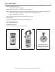
Tools Required • • Electrical multimeter capable of measuring continuity/ ohms, ac & dc volts, amperes, microamperes, millivolts, and frequency (hz) • UEi Model DL289 or equivalent Digital manometer + 60" w. c., resolution 0.01" increments Note: A digital manometer is required for testing pressure switches and can replace a gas pressure gauge, draft gauge or slack tube manometer for checking gas pressure.
INSTALLATION CONSIDERATIONS Gas AND ELECTRICAL CHARACTERISTICS MODELS All Models GAS TYPE Natural GAS SUPPLY PRESSURE MINIMUM MAXIMUM 3.5" WC (0.87 kPa) 14.0" WC (3.48 kPa) VOLTS/HZ AMPERES 120/60 <5 All models require a minimum gas supply pressure of 3.5” W.C. The minimum supply pressure is measured while gas is flowing (dynamic pressure). The supply pressure (dynamic) should never fall below 3.5” W.C.
AIR SUPPLY: Stoichiometric or theoretical complete combustion requires 10 cubic feet of air per 1,000 BTU of gas supplied. The National Fuel Gas Code also recommends an additional 2.5 cubic feet of “excess” air. For information on minimum make-up air opening sizes for various building installations, refer to the National Fuel Gas Code NFPA 54/ANSI Z223.1.
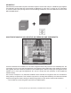
MAKE-UP AIR – DIRECT COMMUNICATION WITH OUTDOORS: A fresh supply of make-up air for combustion can be supplied to the water heater through make-up air ducts, which directly communicate with the outdoors. (Not Direct Vent.) Two openings are required: one within 12 inches (30 cm) of the top of the enclosure and one within 12 inches (30 cm) of the bottom of the enclosure.
AIR REQUIREMENTS: For safe operation an adequate supply of fresh uncontaminated air for combustion and ventilation must be provided. An insufficient supply of air can cause recirculation of combustion products resulting in contamination that may be hazardous to life. Such a condition often will result in a yellow, luminous burner flame, causing sooting of the combustion chamber, burners and flue tubes and creates a risk of asphyxiation.
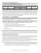
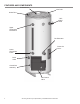
FEATURES AND COMPONENTS Exhaust/Vent Inlet Tube Outlet Tube T&P Relief Valve Upper Thermostat Probe/ECO The Eliminator Clean Out Cover Lower Thermostat Probe Drain Valve Control Box Assembly Gas Gas Control Control ValveValve 8 Servicing should only be performed by a Qualified Service Technician
BLOWER AND BURNER ASSEMBLY Blower Flange Blower Silicone Gasket Burner Gasket Flange Plate Gas Control Valve Brass Locknuts (3) Flame Sensor Burner Spark Igniter Skirt Ring Flange Gasket BURNER REPLACEMENT: 1. Turn off the gas supply and electricity to the water heater and remove the blower cover. 2. Disconnect the spark ignition cable and ground wire plus the flame sensor wire at their connection points on the flange plate. 3.
8. Support the blower and burner assembly in a vertical position with the burner extending downward. 9. Remove the 3 brass locknuts holding the blower adapter to the flange plate. 10. Separate the blower from the flange plate. 11. Clean the flange plate surfaces removing any portions of the old burner gasket. 12. Remove the burner from the flange plate. 13. Insert the new burner into the flange plate and align the notch in the burner flange with the tab in the flange plate. 14.
Spark Igniter, Flame Sensor, Sight Glass The spark igniter and the flame sense rod are shown below. Also shown is the burner sight glass. These features are typical for all models. Sightglass Burner Flame Sensor Spark Igniter SPARK IGNITER / FLAME SENSOR / CONTROL TIMING SPARK IGNITER This water heater is equipped with a spark igniter. Do not damage the ceramic insulator. Inspect the igniter ceramic insulator for any cracks. The spark gap between the spark rod and grounding rod is 1/8".
Venting INSTALLATION – VENTING CATEGORY AND MATERIALS BCL VENTING Category I • Non-condensing, negative pressure in vent, below atmospheric. Type venting • Must be installed Conventional Vent; uses room air for combustion and discharges flue gases to the outdoor atmosphere through one pipe. Vent materials • B Vent.
EXTERIOR CLEARANCES The illustration below shows the required clearances for venting units using natural draft venting. The vent must extend at least 3 feet above the highest point where it passes through a roof of a building and at least 2 feet higher than any portion of a building within a horizontal distance of 10 feet (for vents of 12 inches in diameter or less).
VENTING TABLES – TECHNICAL VENTING DATA TYPE B GAS VENT Multiple Gas Fired Tank-Type Heaters When venting multiple tank type heaters using Type B vent pipe, follow the installation diagram and tables below which give sizing and data based upon NFPA 54 ANSI Z223.1.
OPERATION AND SERVICE SEQUENCE OF OPERATION: 1. Switch power on to unit. 2. Thermostat calls for heat. 3. UGB (Universal Gas Board) sends PWM signal to blower to start the blower. 4. Blower runs at high prepurge speed for 20 seconds. 5. Combustion Blower initiates air flow through water heater closing the Prover Switch. 6. After 30 seconds, the Ignition Control provides power to the Spark Igniter and Gas Valve. 7.
SEQUENCE OF OPERATION – FLOW CHART Switch power on to unit Thermostat calls for heat UGB sends PWM signal to Blower to start the blower at high purge speed Blower engages Prover Switch 20 seconds later blower A er 30 seconds, Igni on Control provides power to Spark Igniter and opens Gas Valve Igni on Control maintains spark for up to 4 seconds and monitors Flame Sensor to determine if Burner is lit NO NO Does Burner light? Gas Valve – off Is this the third igni on trial? Wait 15 minutes.
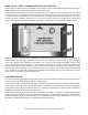
LIGHTING AND OPERATING LABEL FOR YOUR SAFETY READ BEFORE OPERATING WARNING: If you do not follow these instructions exactly, a fire or explosion may result causing property damage, personal injury or loss of life. FLAMMABLE BEFORE OPERATING: ENTIRE SYSTEM MUST BE FILLED WITH WATER AND AIR PURGED FROM ALL LINES. A. This appliance does not have a pilot. It is equipped with an ignition device which automatically lights the burner. Do not try to light the burner by hand. B.
TROUBLESHOOTING COMPLAINT *Water not hot enough. *Insufficient hot water. CAUSE USER Thermostat set too low. Set thermostat dial to a higher temperature Upper and/or lower temperature probe out of calibration. Call qualified agency. Thermostat set too low. Set thermostat dial to a higher temperature *See WATER TEMPERATURE CONTROL WARNING on page Upper and/or lower temperature probe out of 12 of Instruction Manual. calibration. Main manual gas shutoff valve partially closed.
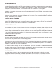
CONTROLS Overview - CONTROL BOX ASSEMBLY ON/OFF Switch Digital Thermostat Blower Prover Switch Ignition Control Pressure Switches – All Models All BCL 120 thru 250 models are provided with one blower prover switch with +0.38" w.c. setpoint. The blower prover switch is provided on the heater to verify that the fan is operating. It is a positive pressure switch whose electrical contacts are normally open.
HIGH LIMIT SWITCH/ DIGITAL THERMOSTAT The digital thermostat contains the high limit (energy cut out) switch. The high limit switch interrupts burner gas flow should the water temperature reach 203°F (95°C). In the event of high limit switch operation, the water heater cannot be restarted unless the water temperature is reduced to approximately 120°F (49°C). The manual reset button on the front of the control then needs to be depressed.
DISPLAY LIGHTS – DIGITAL THERMOSTAT LED STATUS INDICATION Calling for heat The ECO (Energy Cut-Out) has opened. ACTION Normal status. No action required. • Check for excessively hot water (203° F or higher). • Check the resistance of the temperature probes and continuity of the high limit (ECO). No power Check the breaker. Tank is at a set temperature ± 2° F. No action required. Tank has cooled below 120° F. Preceded by “ECO Open” indication. • Push the manual reset button.
CONTINUITY CHECK OF HIGH LIMIT (ECO) CONDITIONS: • Power On – No Hot Water. • Red, digital thermostat “Call for Heat” LED – On. • Turn Power OFF. Continuity check of ECO (energy cut-out, high limit) Black to Black wires of upper probe. Power is off. IF......... THEN............ Continuity is indicated (ZERO “0.0” Resistance) Continuity is not present (meter reads “0.L”) Water is less than 120° F Opens at 203° F; closes at 193° F. If water is below 193° F, continuity is correct.
UPPER TEMPERATURE PROBE CONTINUITY CHECK CONDITIONS: • Power On – Water below temperature set point. • Red, digital thermostat “Reset Status” LED – OFF. • "Call for Heat" LED Off. OHMS RESISTANCE TABLE °F OHMS 70° 120° 140° 180° 11,884 3,759 2,488 1,169 Upper Temperature Probe continuity check Red wire to red wire – Turn supply power "Off" for this test. IF......... THEN............ Test indicates no continuity. Continuity is indicated. Replace probe.
LOWER TEMPERATURE PROBE CONTINUITY CHECK CONDITIONS: • Main burner ignited. • Stored water is below temperature setting more than 5° F (Tank Average). • Power Off. • Plug disconnected from digital thermostat receptacle E4. OHMS RESISTANCE TABLE °F OHMS 70° 120° 140° 180° 11,884 3,759 2, 488 1, 169 Lower Temperature Probe continuity check Red wire to red wire – Turn supply power "Off" for this test. IF......... THEN............ Test indicates no continuity. Continuity is indicated.
IGNITION CONTROL Each heater is equipped with an ignition control. The solid state ignition control, ignites the burner by utilizing a spark igniter. The spark igniter shuts off during the heating cycle and the burner flame is sensed through a remote flame sensor. The ignition control will try to ignite the burner three times before lockout. The control waits 15 minutes before trying again to ignite the burner. This is a continuous cycle. This is a 24 VAC ignition control.
START UP/ FLAME RECOVERY/ SAFETY LOCKOUT START UP - HEAT MODE When a call for heat is received from the thermostat supplying 24 volts to to UGB J5.6, the UGB will enable blower run at prepurge speed, which will cause the blower prover switch closing, and allow 24vac power from the T-stat to TH/W terminal of the control module. The control will reset, perform a self check routine, flash the diagnostic LED once in the first two seconds, and a pre-purge delay begins.
FAULT CONDITIONS The water heater is equipped with an ignition control that incorporates a diagnostic system to assist in troubleshooting the appliance. The indicator codes on the ignition module are as follows: LED INDICATION 2 Flashes 3 Flashes Steady On FAULT MODE Flame sensed without call for heat. Ignition Lockout. Internal Control Failure The LED will flash on for 1/4 second, then off for 1/4 second during a fault condition. The pause between fault codes is 3 seconds.
UGB – BLOWER SPEED CONTROL The BCL 120 thru 250(A) models are equipped with a UGB PWM output control board for blower speed control. When the UGB J5.6 is energized by T-stat Call-for-heat, the UGB will provide 90% duty cycle PWM signal to the blower for 20 seconds prepurge, then provide a PWM control signal per SW2 dipswitch setting for igntion speed. After the flame is confirmed and the UGB J5.
WIRING DIAGRAM Servicing should only be performed by a Qualified Service Technician 29
COMMERCIAL GAS WATER HEATERS Visit the "Information Central" link of www.americanwaterheater.com for a listing of available Service Handbooks. For additional information contact: American Water Heaters PO Box 1597, 500 Princeton Road Johnson City, TN 37605 1-800-456-9805 www.americanwaterheater.