Instruction Manual RESIDENTIAL DIRECT VENT GAS W ATER HEA TERS WA HEATERS FOR USE ONLY IN MANUFACTURED HOMES FOR USE ONLY WITH VENTING SYSTEMS SUPPLIED WITH THE WATER HEATER WHETHER A NEW INSTALLATION OR A REPLACEMENT INSTALLATION. GAMA certification applies to all residential gas water heaters with capacities of 20 to 100 gallons with input rating of 75,000 BTU/Hr. or less. • For Your Safety • AN ODORANT IS ADDED TO THE GAS USED BY THIS WATER HEATER.
SAFE INST ALLA TION INSTALLA ALLATION TION,, USE AND SERVICE Your safety and the safety of others is extremely important in the installation, use and servicing of this water heater. Many safety-related messages and instructions have been provided in this manual and on your own water heater to warn you and others of a potential injury hazard. Read and obey all safety messages and instructions throughout this manual.
GENERAL SAFETY 3
TABLE OF CONTENTS Fuel Conversion Instructions from Propane (L.P.) to Natural Gas ....................................................................... 19 LIGHTING & OPERATING LABEL .............................................. 20 TEMPERATURE REGULATION ................................................... 21 FOR YOUR INFORMATION ................................................... 21-22 Start Up Conditions ............................................................... 21 Condensate .......................
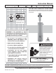
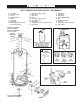
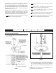
TYPICAL INST ALLA TION INSTALLA ALLATION GET TO KNOW YOUR WATER HEATER - GAS MODELS A B C D E F G H I Vent Pipe Securing Clamp Anode Hot Water Outlet Outlet Roof Jack Gas Supply Manual Gas Shut-off Valve Ground Joint Union J K L M N O P Q R Drip Leg (Sediment Trap) Inner Door Outer door Union Inlet Water Shut-off Valve Cold Water Inlet Inlet Nipple Temperature-Pressure Relief Valve Rating Plate * INSTALL IN ACCORDANCE WITH LOCAL CODES.
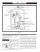
TYPICAL INST ALLA TION INSTALLA ALLATION * MIXING VALVE USAGE FIGURE 2. This appliance has been design certified as complying with American National Standard/CSA Standard ANSI Z21.10.1 • CSA 4. 1 for water heaters and is considered suitable for: HOTTER WATER CAN SCALD: Water heaters are intended to produce hot water. Water heated to a temperature which will satisfy space heating, clothes washing, dish washing, and other sanitizing needs can scald and permanently injure you upon contact.
LOCA TING THE NEW W ATER HEA TER OCATING WA HEATER have no more than 3 elbows. All horizontal runs require adequate support at 3 1/2 feet intervals., see Figure 4. FACTS TO CONSIDER ABOUT THE LOCATION Whether replacing an old water heater or putting the water heater in a new location, the following critical points must be observed. This manufactured home gas-fired water heater is for use in a manufactured home.
alcove or closet, the entire floor must be covered by the panel. Failure to heed this warning may result in a fire hazard. These devices are available from some plumbing supply wholesalers and retailers, and detect and react to leakage in various ways: • Sensors mounted in the drain pan that trigger an alarm or turn off the incoming water to the water heater when leakage is detected.
Insulation blankets are available to the general public for external use on gas water heaters but are not necessary with these products. The purpose of an insulation blanket is to reduce the standby heat loss encountered with storage tank heaters. Your water heater meets or exceeds the National Appliance Energy Conversation Act standards with respect to insulation and standby loss requirements, making an insulation blanket unnecessary.
4. Set the water heater in place against the lip of the duct assembly as shown in Figure 11. FIGURE 11. FIGURE 7. 5. Secure the water heater to the duct assembly using the screw provided. NOTE: See pages 12 and 13 for installing an air intake through an outside wall when the manufactured home is located over a basement or crawl space.
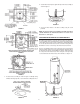
ROOF JACK INSTALLATION ROOF JACK KIT MODELS VENT KIT- 12 INCH (9002964), VENT KIT - 32 INCH (9002965), VENT KIT - 60 INCH (9002966) AND VENT KIT - 95 INCH (9002967) FIGURE 13. 4. Ease the roof jack assembly through the roof and ceiling openings. The roof jack flashing tilts up to 22.6° degrees for use on a sloping roof. 1. Cut 5 1/2” diameter holes through the roof and ceiling directly in line with the flue connection on top of the water heater.
ALL MODELS 1. PVC, ABS or CPVC Schedule 40 piping and fittings are acceptable materials for the intake air vent system. 2. The intake air vent system must terminate horizontally to the outdoors. 3. Remove the screws which attach the wind baffle to the existing metal air intake vent pipe underneath the home. Discard the wind baffle and screws, see Figure 19. FIGURE 16. 7. Extend the flue pipe down close to the water heater flue collar, see Figure 17. FIGURE 17. 8.
NOTE: Vent cap must be located a minimum of 12” above the ground. INSTALLATION SHOWING USE OF PVC, ABS OR CPVC PIPE 5. Vertical and horizontal runs must be securely supported at 3 1/2 Foot intervals, see Figure 21. FIGURE 23. NOTE: Wall collars are for aesthetic purposes and are not required for the heater to operate. FIGURE 21. CEMENTING PVC, ABS OR CPVC PIPE AND FITTINGS 6. The intake air vent piping can be installed with no more than 3 elbows, see Figure 22.
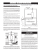
APPROXIMATE SETTING TIME FOR 2 1/2” TO 4” PIPE JOINTS 90°F TO 150°F 50°F TO 90°F 0°f TO 50°F MOVEMENT OF JOINT 3/4HR. 1 HR. 1 1/3 HR. The water within the water heater tank expands as it is heated and increases the pressure of the water system. If the relieving point of the water heater’s temperature-pressure relief valve is reached, the valve will relieve the excess pressure. The temperature-pressure relief valve is not intended for the constant relief of thermal expansion.
Secure all insulation using tape. TEMPERATURE-PRESSURE RELIEF VALVE • Temperature-pressure relief valve must comply with ANSI Z21.22 and ASME code. • Properly sized temperature-relief valve must be installed in opening provided. • Can result in overheating and excessive tank pressure. • Can cause serious injury or death. FIGURE 25. WATER PIPING PRESSURE TEST • • This heater is provided with a properly certified combination temperature - pressure relief valve by the manufacturer.
• Shall not be plugged or blocked. FILLING THE WATER HEATER • Shall be of material listed for hot water distribution. • Shall be installed so as to allow complete drainage of both the temperature-pressure relief valve, and the discharge pipe. • Shall terminate at an adequate drain. • Shall not have any valve between the relief valve and tank. Never use this water heater unless it is completely full of water. To prevent damage to the tank, the tank must be filled with water.
There must be: • • • A sediment trap shall be installed as close to the inlet of the water heater as practical at the time of water heater installation. The sediment trap shall be either a tee fitting with a capped nipple in the bottom outlet or other device recognized as an effective sediment trap. If a tee fitting is used, it shall be installed in conformance with one of the methods of installation shown in Figures 28,29 and 30.
INJURY, OR PROPERTY DAMAGE. If you have any questions or doubts consult your gas supplier or gas company. Step 10. Turn gas control knob clockwise to “OFF” position. Knob cannot be turned from “PILOT” to “OFF” unless knob is depressed slightly. DO NOT FORCE. Read and follow detailed conversion instructions located on the water heater and also in the instruction manual in their entirety before starting the conversion. Step 11. Wait five minutes to clear out any gas.
FIGURE 31. Step 21. Replace the outer door if not replaced in Step 17. Step 22. Remove adhesive label found in conversion kit and place next to rating plate. Mark label indicating for which type gas the water heater is now equipped. FUEL CONVERSION INSTRUCTIONS FROM PROPANE (L.P.) GAS TO NATURAL GAS This water heater has been factory equipped to operate with the type gas indicated in the “EQUIPPED FOR” area of the model rating plate located near the gas control valve.
TEMPERA TURE REGULA TION TEMPERATURE REGULATION Short repeated heating cycles caused by small hot water uses can cause temperatures at the point of use to exceed the thermostat setting by up to 30°F (16.7°C). If you experience this type of use you should consider using lower temperature settings to reduce scald hazards. NOTE: A water temperature range of 120°F-140°F (49°C-60°C) is recommended by most dishwasher manufacturers. The thermostat of this water heater has been factory set at its lowest position.
Excessive condensation may be noticed during the winter and early spring months when incoming water temperatures are at their lowest. most common complaint associated with the anode rod is one of a “rotten egg smell” in the hot water. This odor is derived from hydrogen sulfide gas dissolved in the water.
PERIODIC MAINTENANCE VENTING SYSTEM INSPECTION You should check for sooting. Soot is not normal and will impair proper combustion. Soot build-up indicates a problem that requires correction before further use. Turn “OFF” gas to water heater and leave off until repairs are made, because failure to correct the cause of the sooting can result in a fire causing death, serious injury, or property damage. FIGURE 38.
may have a check valve installed in the water line or a water meter with a check valve. Consult your local water supplier or service agency for further information. Do not plug the temperature-pressure relief valve. ANODE ROD INSPECTION DRAINING The anode rod is used to protect the tank from corrosion. Most hot water tanks are equipped with an anode rod. The submerged rod sacrifices itself to protect the tank. Instead of corroding the tank, water ions attack and eat away the anode rod.
SERVICE If a condition persists or you are uncertain about the operation of the water heater contact a service agency. Use this guide to check a “Leaking” water heater. Many suspected “Leakers” are not leaking tanks. Often the source of the water can be found and corrected. If you are not thoroughly familiar with gas codes, your water heater, and safety practices, contact your gas supplier or qualified installer to check the water heater. FIGURE 40. LEAKAGE CHECKPOINTS Read this manual first.
TROUBLESHOOTING GUIDELINES These guidelines should be utilized by a qualified service agent. Problem WATER LEAKS LEAKING T&P VALVE HOT WATER ODORS PILOT OUTAGE PILOT WILL NOT LIGHT NOT ENOUGH OR NO HOT WATER WATER TOO HOT WATER HEATER SOUNDS: SIZZLING - RUMBLING SOOTING Cause Solution Improperly sealed, hot or cold supply connection, relief valve, drain valve, or thermostat threads. Leakage from other appliances or water lines. Condensation of flue products.
REP AIR P ARTS LIST REPAIR PARTS Key No. 1 2 3 4 5 6 7 8 8 9 10 11 #12 13 14 15 16 17 18 19 #20 #20 21 21 22 23 24 24 24 24 25 26 27 28 29 30 * # Part Description Air Duct Assembly (12” to 24” Long) Angle Bracket (2 Required) Angle Bracket Anode Rod Sight Glass Assembly Burner Burner Manifold Burner Orifice (Natural Gas) Burner Orifice (Propane [L.P.