TM HEATERS Gas Water Heater with the Flame Lock TM Safety System Installation Instructions and Use & Care Guide WARNING: If the information in these instructions is not followed exactly, a fire or explosion may result causing property damage, personal injury or death. Do not store or use gasoline or other flammable vapors and liquids in the vicinity of this or any other appliance. WHAT • + TO DO IF YOU SMELL GAS Do not try to light any appliance.
Your safety and the safety of others are very important. We have provided many important safety messages in this manual and on your appliance. Always read and obey all safety messages. This is the safety alert symbol. This symbol alerts you to potential hazards that can kill or hurt you and others. All safety messages will follow the safety alert symbol and either the word "DANGER" or "WARNING" These words mean: You can be killed or seriously injured if you don't immediately follow instructions.
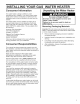
I ;TALL! Consumer YOU GAS EATE information This water heater is design-certified by CSA International as a Category I, non-direct vented water heater which takes its combustion air either from the installation area or from air ducted to the unit from the outside. This water heater must be installed according to all local and state codes or in the absence of local and state codes with the "National Fuel Gas Code", ANSI Z223.1 (N FPA 54)- latest edition.
Location Requirements Carbon Dioxide Poisoning Hazard Do not install in a mobile home. Doing so can result in death or carbon monoxide poisoning. _lLVapors from explode and catch severe burns. flammable fire liquids causing will death or Do not use or store flammable products such as gasoline, solvents or adhesives in the same room or area near the water heater. Keep flammable products: 1. far away from heater 2. in approved containers, 3. tightly closed and 4. out of children's reach.
Important:Thewaterheatershouldbelocatedinan areawhereleakageofthetankor connections will not resultindamageto theareaadjacenttothewater heateror tolowerfloorsof thestructure.Duetothe normalcorrosiveactionofthewater,thetankwill eventually leakafteranextendedperiodoftime.A suitablemetaldrainpanshouldbeinstalledunderthe waterheaterasshownbelow,tohelpprotectthe propertyfromdamagewhichmayoccurfrom condensate formationor leaksinthe piping connections ortank.
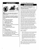
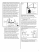
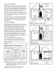
Gas Supply Figure 3 Gas Piping Manual Gas c:::3 Sh ut-off Valve [ Ground Joint _---_ Union Check with local utility for min. height Explosion Use a new AGA or CSA approved supply line. Install a shut-off valve. gas Do not connect a natural gas water heater to a L.P. Gas Supply. Failure to follow these instructions can result in death, explosion, or carbon monoxide poisoning. OBSERVE ALL GOVERNING 1 Hazard 3 in. min.
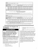
Table 1 Natural Gas Pipe Capacity Table (Cu. Ft./hr) Capacity of gas pipe of different diameters and lengths in cu. ft. per hr. with pressure drop of 0.3 in. and specific gravity of 0.60 (natural gas). Nominal Iron Pipe Size, in.
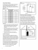
Unconfined Figure 4 Opening LocationsConfined Spaces Space A water heater in an unconfined space uses indoor air for combustion and requires at least 50 cubic feet for each 1,000 BTUH of the total input for all gas appliances. The table below shows a few examples of the minimum square footage (area) required for various BTUH inputs.
All Air from Gable Outdoors vent to outdoors Outdoor fresh air can be provided to a confined area either directly or by the use of vertical and horizontal ducts. The fresh air can be taken from the outdoors or from crawl or attic spaces that freely communicate with the outdoors. Attic or crawl spaces cannot be closed and must be properly ventilated to the outside. Ductwork must be of the same cross-sectional area as the free area of the opening to which they connect.
Vent Pipe System Vent Pipe Size This water heater uses a non-direct, single-pipe vent system to remove exhaust gases created by the burning of fossil fuels. Air for combustion is taken from the immediate water heater location or is ducted in from the outside (see "Combustion Air Supply and Ventilation"). The vent pipe must be installed according to all local and state codes or in absence of local and state codes with the "National Fuel Gas Code", ANSI Z223.1 (NFPA54)-Iatest edition.
Chimney Connection Important: Before connecting a vent to a chimney, make sure the chimney passageway is clear and free of obstructions. The chimney must be cleaned if previously used for venting solid fuel appliances or fireplaces. • The connector must be installed above the extreme bottom of the chimney to prevent potential stoppage of the flue gases. The connector must be firmly attached and sealed to prevent it from falling out.
Water System Piping Piping Installation Piping, fittings, and valves should be installed according to the installation drawing (Figure 13). If the indoor installation area is subject to freezing temperatures, the water piping must be protected by insulation. Water supply pressure should not exceed 80% of the working pressure of the water heater. The working pressure is stated on the water heater's data plate.
Pleasenotethefollowing: DONOTinstallthiswaterheaterwithironpiping. Thesystemshouldbeinstalledonlywithnewpiping thatis suitableforpotable(drinkable) watersuchas copper,CPVC,or polybutylene. DONOTusePVC waterpiping. DONOTuseanypumps,valves,or fittingsthatare notcompatible withpotablewater. DONOTusevalvesthatmaycauseexcessive restriction towaterflow.Usefullflowballor gate valvesonly. DONOTuse50/50tin-leadsolder(oranylead basedsolder)inpotablewaterlines.Use95/5tinantimonyorotherequivalent material.
Temperature Relief Valve and Pressure Important: Only a new temperature and pressure relief valve should be used with your water heater. Do not use an old or existing valve as it may be damaged or not adequate for the working pressure of the new water heater. Do not place any valve between the relief valve and the tank. The Temperature Explosion Hazard If the temperature and pressure relief valve is dripping or leaking, have a licensed plumber repair it. Do not plug valve. Do not remove valve.
Special Applications Combination Space Heating/Potable Water System Some water heater models are equipped with inlet/outlet tappings for use with space heating applications. If this water heater is to be used to supply both space heating and domestic potable (drinking) water, the instructions listed below must be followed. • Be sure to follow the manual(s) shipped with the air handler system. • This water heater is not to be used as a replacement for an existing boiler installation.
installation Checklist Water • Heater Location Vent Pipe System Centrally located with the water piping system. Located as close to the gas piping and vent pipe system as possible. • Drafthood properly installed. • Vent connectors securely fastened with screws and supported properly to maintain 6 inch clearance. ,, Located indoors and in a vertical position. Protected from freezing temperatures. ,, Vent connector made of approved material and sized correctly.
OPE Lighting G YOUR EATE instructions LP.G. Read and understand these directions thoroughly before attempting to light or re-light the pilot. Make sure the tank is completely filled with water before lighting the pilot. Check the data plate near the gas valve control/thermostat for the correct gas. Do not use this water heater with any gas other than the one listed on the data plate. If you have any questions or doubts, consult your gas supplier or gas utility company.
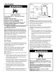
Checking the Draft Water Temperature Regulation Burn Hazard Do not touch vent. Doing so can result burns. in After successfully lighting the water heater, allow the unit to operate for 15 minutes and check the drafthood relief opening for proper draft. Pass a match flame around the relief opening of Figure 17 the drafthood. A steady Relief flame drawn into the opening indicates proper draft. If the flame flutters or is blown out, combustion Ma_ Opening products are escaping from the relief opening.
Operational Conditions Condensation Moisture from the products of combustion condenses on the tank surface and the outside jacket of the water heater and forms drops of water which may fall onto the burner or other hot surfaces. This will produce a "sizzling" or "frying" noise. This condensation is normal and should not be confused with a leaking tank. Condensation may increase or decrease at different times of the year.
NTENANCE Draining OF YOU and Flushing It is recommended that the tank be drained and flushed every 6 months to remove sediment which may buildup during operation. The water heater should be drained if being shut down during freezing temperatures. To drain the tank, perform the following steps: 1. Turn off the gas to the water heater at the Manual Gas Shut-off Valve. 2. Close the cold water inlet valve. 3. 4. Open a nearby hot water faucet.
Replacement Parts Figure 22 Burner Assembly Removal The following maintenance procedures are for the Flame Lock TM safety system components and should be performed by a qualified service technician. Gas Valve Thermostat Model, serial and product number. 2. Type of gas. 3. Item number. 4. Parts description. / Turn off the gas to the water heater at the manual shut-off valve (Figure 3). 2.
Natural 1. . Gas Burner (Low Nox) Replacing Take off the burner by removing the two(2) screws located underneath the burner. Check the burner to see if it is dirty or clogged. The burner may be cleaned with soap and hot water (Figure 23B). Figure Natural 23B Gas (Low Burner Manifold Door Assembly Nox) Assembly Important: Use only a factory authorized Flame Lock TM safety system thermocouple for replacement. 1. Remove the manifold assembly as directed previously. 2.
Cleaning the Combustion and Flame-trap Chamber 1. Follow procedure outlined in "Removing the Manifold Assembly". 2. Use a vacuum cleaner/shop vac to remove all loose debris in the combustion chamber and flame-trap. See Figure 26. 3. Reassemble following the procedure under "Replacing the Manifold Assembly". Replacing the Manifold Assembly FI Figure 26 _, , Combustion Chamber 4. . . Explosion Hazard Tighten both manifold door screws securely.
Piezoelectric Igniter System The piezoelectric igniter system is part of the Flame Lock TM safety system and consists of the igniter button, electrode and wire. The pilot is ignited by an electric spark generated when the igniter button is pressed. The spark gap of 0.125 inch is set when the electrode is installed at the factory. (See Figure 27Aand 27B). Use only factory authorized Flame Lock TM safety system piezoelectric igniter parts for replacement.
Flame 1. 2. 3. 4. 5. 6. Lock TM Safety System Operational Checklist Manifold gasket properly sealed. Viewport not damaged or cracked. Flame-trap free of debris and undamaged. Two piece wire connector properly installed. No leaks at pilot and manifold connection. Manifold door screws securely tightened. TROUBLESHOOTING PROBLEM CHART CORRECTIVE ACTION POSSIBLE CAUSE(S} BURNERWILL NOT IGNITE 1. 2. 3. 4. 5. 6. 7. 8. 9.
TROUBLESHOOTING PROBLEM SLOWHOTWATER RECOVERY POSSIBLE CAUSE(S} CORRECTIVE ACTION 1. Insufficientsecondaryair 1. 2. 3. 4. 5, 6. 7, 8. Flueclogged Lowgas pressure Impropercalibration Thermostatset too low Waterheatertoo small Wrongpipingconnections Wastedhot water 2. 3. 4. 5, 6. 7, 8. Provideventilationto waterheater.
PARTS ILLUSTRAT! location for top T&P Alternate anode ___ Anode location for side T & P When ordering repair parts always give the following information: 1. Model, serial, and product number 2. Type of gas 3. Item number 4. Parts description Repair Parts List item No.
Listed Part Kits and Illustrations item 11: Pilot assembly/thermocouple kit, which contains the pilot assembly with piezoelectric igniter, thermocouple, and retainer clip. (Natural Gas) item 12: Pilot assembly/thermocouple kit, which contains the pilot assembly with piezoelectric igniter, thermocouple, and retainer clip. (LR Gas) item 14: Manifold burner assembly which contains the manifold tube, gasket, door, pilot tube, thermocouple, two piece wire connector with retainer clip, and pilot assembly.